External fixator for immobilizing bone fragments, particularly in the area of the wrist

a fixator and bone technology, applied in the field of external fixators for immobilizing bone parts, can solve the problems of affecting the production cost of fixators, the relative complexity of structures, and the inability to provide fixators to be discarded,

Inactive Publication Date: 2003-03-11
STRYKER EURO OPERATIONS HLDG LLC
View PDF12 Cites 112 Cited by
  • Summary
  • Abstract
  • Description
  • Claims
  • Application Information

AI Technical Summary

Benefits of technology

This fixator therefore has a very simple structure and is particularly easy to manufacture. The resulting low cost allows this fixator to be used once and discarded and, consequently, makes it possible to eliminate all sterilization operations.
The first pin-holder assembly can slide and pivot relative to the bar and can therefore be placed in any required position relative to a long bone, in particular the humerus; the second pin-holder assembly is movable by pivoting relative to the bar in the three spatial planes, which permits any desired orientation of the pins, for insertion in the bone part concerned, in particular a fragment of the humerus or a metacarpal. The fixator according to the invention thus has very wideranging possibilities of movement of the pin-holder assemblies and of spatial orientation of the pins, so that its very simple structure, which is inexpensive to manufacture, does not in any way lessen its possibilities of use.
The pin-holder assemblies, by virtue of their one-piece structure, can be obtained by relatively simple cutting, drilling and tapping operations.
In addition, this fixator is quick and easy to dismantle and re-fit in a case where re-use is desired, involving sterilization.
The means by which it is possible to immobilize said second pin-holder assembly in a defined position relative to the bar can themselves consist, in an identical fashion, of a tapped hole formed substantially perpendicular to said recess and opening into the latter, and of a screw which can be received in this hole, this screw, when tightened, making it possible to clamp the spherical part of the bar in the recess.

Problems solved by technology

This type of fixator is satisfactory in practice but has the disadvantage of having a relatively complex structure, which is not without impact on its production cost.
This fixator cannot therefore be provided to be discarded after a single use, which means that it has to be sterilized after each use.
This sterilization involves dismantling and re-fitting the fixator, which are relatively awkward operations, and requires that the fixator be kept in a suitable sterile packaging between two uses.

Method used


Image

  • External fixator for immobilizing bone fragments, particularly in the area of the wrist
  • External fixator for immobilizing bone fragments, particularly in the area of the wrist
  • External fixator for immobilizing bone fragments, particularly in the area of the wrist

Examples


Embodiment Construction

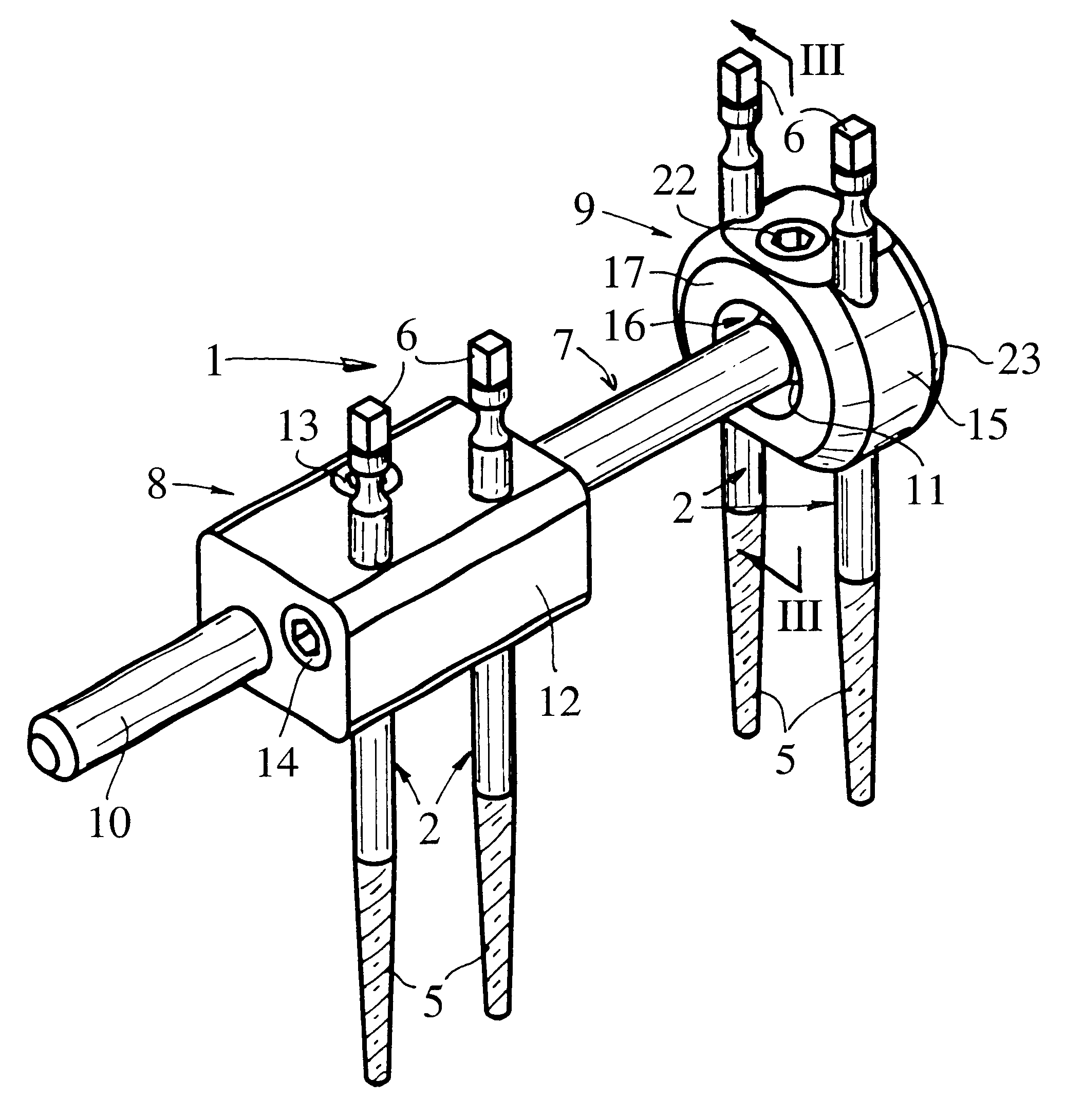
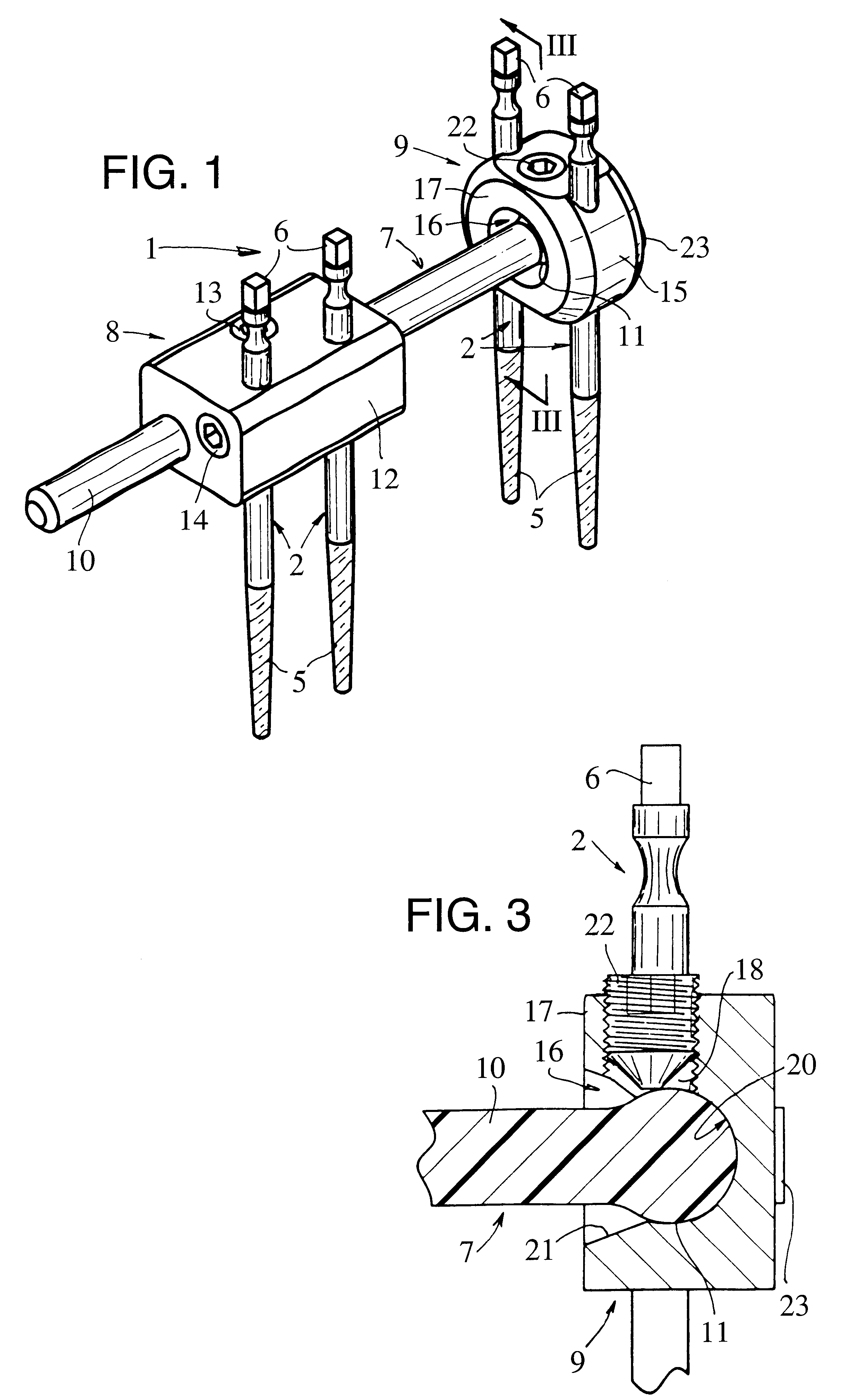
FIGS. 1 to 3 represent an external fixator 1 with which it is possible to maintain two bone parts relative to one another by means of pins 2 inserted in these bone parts. In the example shown in FIG. 2, the fixator 1 is used to immobilize a humerus fragment 3 relative to the rest of the bone with a view to repairing the fracture 4.

The pins 2 are of conventional type. Each of them comprises a self-drilling part 5 permitting its insertion in the cortical substance of a bone, and a square head 6 allowing it to be maneuvered in rotation.

The fixator 1 comprises a rigid bar 7 and two pin-holder assemblies 8, 9.

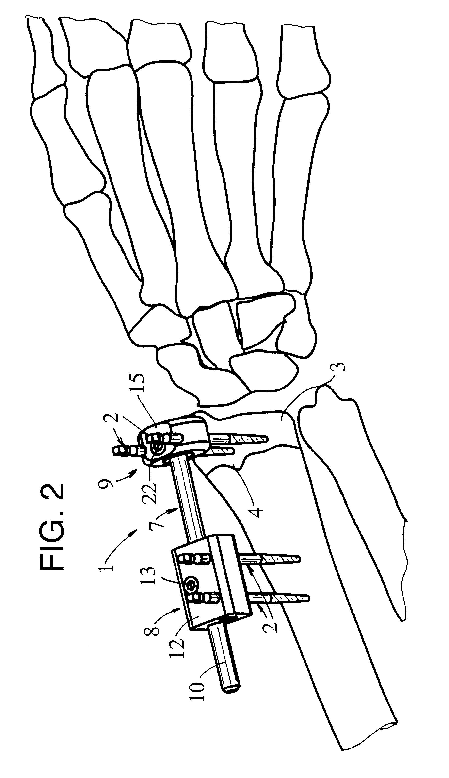
The bar 7 is made of a resin reinforced with carbon fibers and is molded in such a way as to present a cylindrical main part 10 and a spherical part 11 at one end.

The assembly 8 comprises a one-piece body 12 made of synthetic or metal material.

This body 12 has a bore passing through it to permit its engagement by sliding on the part 10 and its pivoting about the latter, and a tapped...


PUM


Abstract

This fixator (1) comprises a rigid bar (7), two pin-holder assemblies (8, 9) which can be moved relative to this bar (7), and means (13, 22) with which it is possible to immobilize each pin-holder assembly (8, 9) in a defined position relative to the bar (7).According to the invention:the bar (7) has a cylindrical main part (10) and a spherical part (11) at one end;a first pin-holder assembly (8) comprises a one-piece body (12) with a bore passing through it to permit its engagement by sliding on the cylindrical part (10) of the bar (7); andthe second pin-holder assembly (9) comprises a one-piece body (15) in which a recess (16) is formed, this recess (16) having a zone of partially spherical shape with a radius slightly greater than that of said spherical part (11), this zone being such that it can receive this spherical part (11) with pivoting, without lateral play, and with a possibility of articulation of said second pin-holder assembly (9).

Description

1. Field of the InventionThe present invention relates to an external fixator for immobilizing bone parts, particularly in the area of the wrist.2. Description of Related ArtA fixator exists with which it is possible to immobilize bone parts in the area of the wrist, comprising a bar and two pin-holder assemblies which can slide and pivot relative to this bar. To allow the pins to be oriented in all the desired directions depending on the immobilization to be performed, each pin-holder assembly is mounted on a slotted ring of spherical outer shape, engaged and able to slide on the bar, and comprises two jaws, one of which is intended to receive and clamp the pins, and the other of which is intended to surround and clamp this ring.With the second jaw in the loosened state, the ring permits each pin-holder assembly to slide along the bar and allows this assembly to pivot about the ring in the three spatial planes. Tightening of this second jaw makes it possible, by clamping the ring o...

Claims


Application Information

Patent Timeline
Patent Type & Authority Patents(United States)
IPC IPC(8): A61B17/60A61B17/64
CPCA61B17/60A61B17/6466A61B17/6458A61B17/6425
Inventor BOUDARD, FREDERICFRITSCH, BERTRANDTHOMAS, CHRISTIANTOLEDANO, ELIELEBRUN, CHRISTOPHEBERRET, MICHELMARTIN, JEAN-JACQUES
Owner STRYKER EURO OPERATIONS HLDG LLC
Why Eureka
Try Eureka