Sewing machines

Inactive Publication Date: 2003-03-18
TOKAI IND SEWING MACH CO LTD
View PDF12 Cites 14 Cited by
  • Summary
  • Abstract
  • Description
  • Claims
  • Application Information

AI Technical Summary

Problems solved by technology

It is very difficult to position the aforementioned drive ring and the frame having a small diameter as near as possible to the outer peripheral surface of the cylinder bed and still support the drive ring, such that the drive ring can stably rotate.
In addition, when such a small frame rotates together with the tubular object around the cylinder bed during the sewing operation, the tubular object (interlining) may be caught and block the edge of the throat plate or the boss portion of the needle hole that protrudes from the surface of the throat plate.
As a result, it is difficult to suitably perform a sewing oper

Method used


Image

  • Sewing machines
  • Sewing machines
  • Sewing machines

Examples


first embodiment

the present invention will be described with reference to FIGS. 1 to 8.

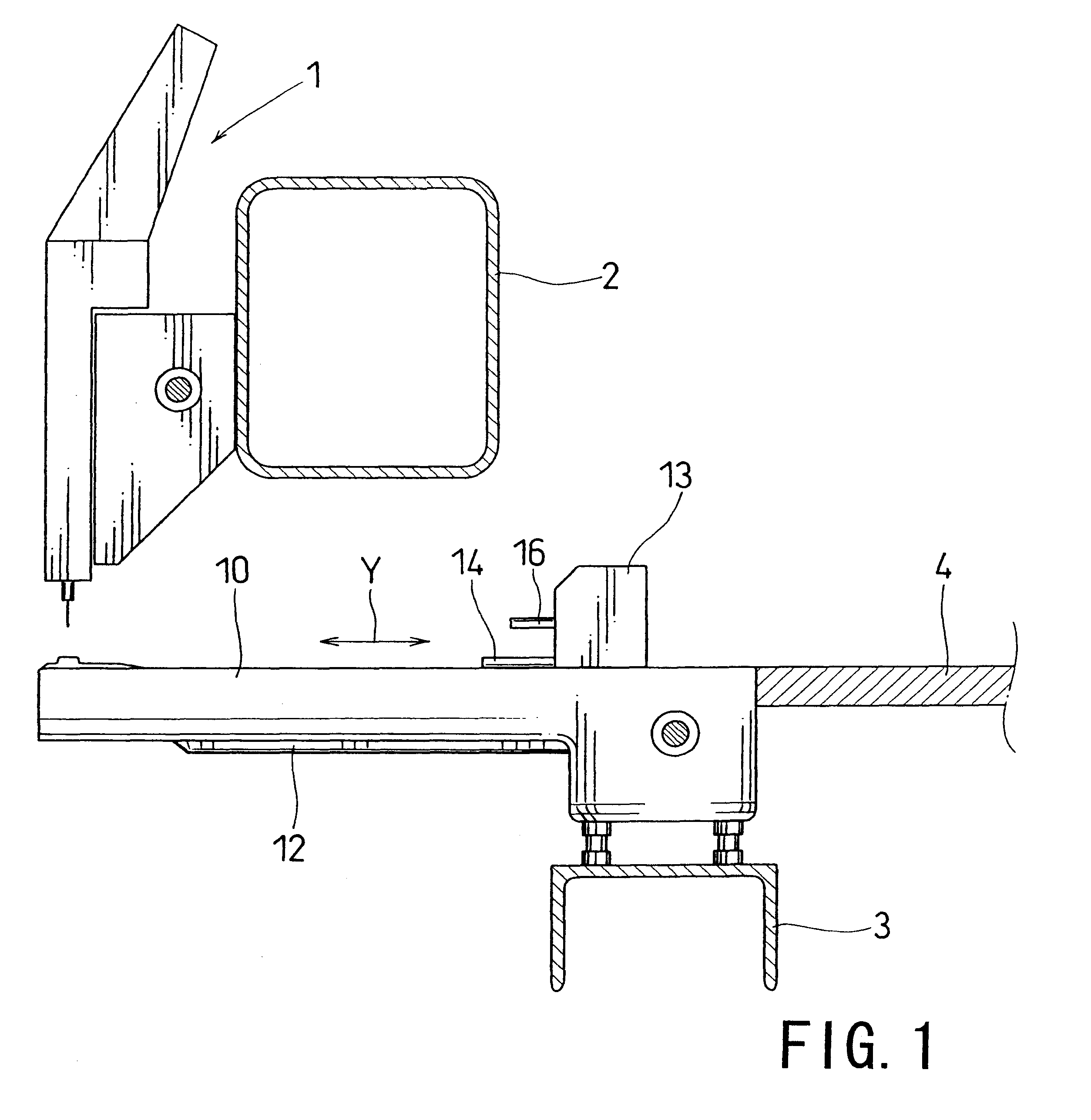
FIG. 1 is a side view that schematically shows a sewing machine, in which a sewing head 1 is disposed on the front side of a machine frame 2; the machine frame 2 supports the sewing head 1. In the case of a multi-head sewing machine, a plurality of sewing heads may be disposed on the machine frame 2. A cylinder bed 10 is disposed at a position below the sewing head 1 and has a base that is supported by the upper surface of a leg structure 3; adjustment is made so that the upper surface of the cylinder bed 10 and the upper surface of the machine table 4 extend substantially in parallel with each other. A drive section 13 is arranged so that it can reciprocally move along these upper surfaces in the direction of arrow Y as shown in FIG. 1; the drive section 13 includes two joint plates 14 and 16.

The drive section 13, which includes the joint plates 14 and 16, has a predetermined length in the direction that is perp...

third embodiment

the present invention will now be described with reference to FIG. 14. The third embodiment, as well as fourth to seventh embodiments that will be explained hereinbelow, relate to modifications of the frame 50.

FIG. 14 is a side view showing a frame 50 according to the third embodiment. In the third embodiment, sewing windows 52 are formed on both the upper and lower sides of receiver frame 51. Accordingly, presser frames 58 and 62 are disposed on each of the upper and lower sides; retainer plates 70 (or recesses 72) are associated with these frames and are provided in pairs on each of upper and lower sides. According to this arrangement, the embroidering operation or the like can be performed individually within each of the upper and lower sewing windows 52 without the need to reset the tubular object on the frame 50, thereby improving operation efficiency.

fourth embodiment

the present invention will now be described with reference to FIGS. 15 and 16.

FIG. 15 is a side view of frame 50 according to the fourth embodiment and FIG. 16 is a perspective view showing only presser frame 58A for interlinings. Although receiver frame 51 and presser frame 62 for tubular objects of this fourth embodiment are the same as those of the first embodiment, the presser frame 58A for interlinings is removably mounted on the receiver frame 51. As will be understood from FIG. 8, the presser frame 58A has a construction, in which both sides of bars 59A are connected together with a pair of front and rear arc-shaped portions 60A. The bars 59A may be fitted into recesses 72 of the retainer plates 70 with both ends of the interlining clamped by the bars, so that the interlining can be retained.


PUM


Abstract

According to the present invention, in a sewing machine, a cylindrical frame for retaining tubular objects is mounted integrally on a cylindrical drive ring that is reciprocally driven in a rotational direction around a cylinder bed and that is linearly reciprocally driven along an axis of the cylinder bed; the drive ring is rotatably supported by a support member that is arranged to contact the outer periphery of the drive ring at three or more positions. By utilizing this construction, not only the drive ring, but also the frame that is mounted thereon may have a small diameter, and the drive ring can be stably supported by the support member so that it smoothly rotates. As a result, the frame can retain tubular objects having a small diameter, such as golf club covers and wrist bands, and a sewing operation, such as an embroidery operation, can be suitably performed along the periphery of the tubular object.

Description

CROSS-REFERENCEThis application is the US National Stage filing of PCT Application Serial Number PCT / JP99 / 05721, which PCT application claims priority to Japanese Patent Application Serial Numbers 11-61915, 11-128939 and 11-165863.The present invention relates to sewing machines that are capable of forming stitches or embroidery on a peripheral surface of a tubular that will be sewn (tubular objects), and in particular, a tubular article that has a small diameter.RELATED ARTConventionally, if an embroidering operation or the like is performed on the periphery of a tubular object, such as a cap having a large diameter, a tubular frame having a large diameter is also used to support the tubular object. However, the tubular object may also have a small diameter, such as a cover for a golf club or a wrist band. If a sewing operation is performed on such a tubular object having a small diameter, the frame that supports the object also must have a small diameter. The frame is mounted on a...

Claims


Application Information

Patent Timeline
IPC IPC(8): D05C9/04D05C9/00
CPCD05C9/04D10B2501/042D05B39/00
Inventor TAJIMA, IKUOSUZUKI, YUICHIROTAKAGI, HIROFUMIHIRATE, MASAYOSHI
Owner TOKAI IND SEWING MACH CO LTD
Why Eureka
Try Eureka