Optical recording medium having groove and land tracks, and method of manufacturing the same

a technology of optical recording medium and groove, which is applied in the field of optical recording medium, can solve problems such as copy protection technology, and achieve the effect of high quality

Inactive Publication Date: 2003-03-18
PIONEER CORP
View PDF7 Cites 55 Cited by
  • Summary
  • Abstract
  • Description
  • Claims
  • Application Information

AI Technical Summary

Benefits of technology

However, with the ability of readily providing a large amount of high quality copies as mentioned above, there has arisen a serious problem in the development of t

Problems solved by technology

However, with the ability of readily providing a large amount of high quality copies as mentioned above, there has arisen a serious problem in the development of t

Method used


Image

  • Optical recording medium having groove and land tracks, and method of manufacturing the same
  • Optical recording medium having groove and land tracks, and method of manufacturing the same
  • Optical recording medium having groove and land tracks, and method of manufacturing the same

Examples


first embodiment

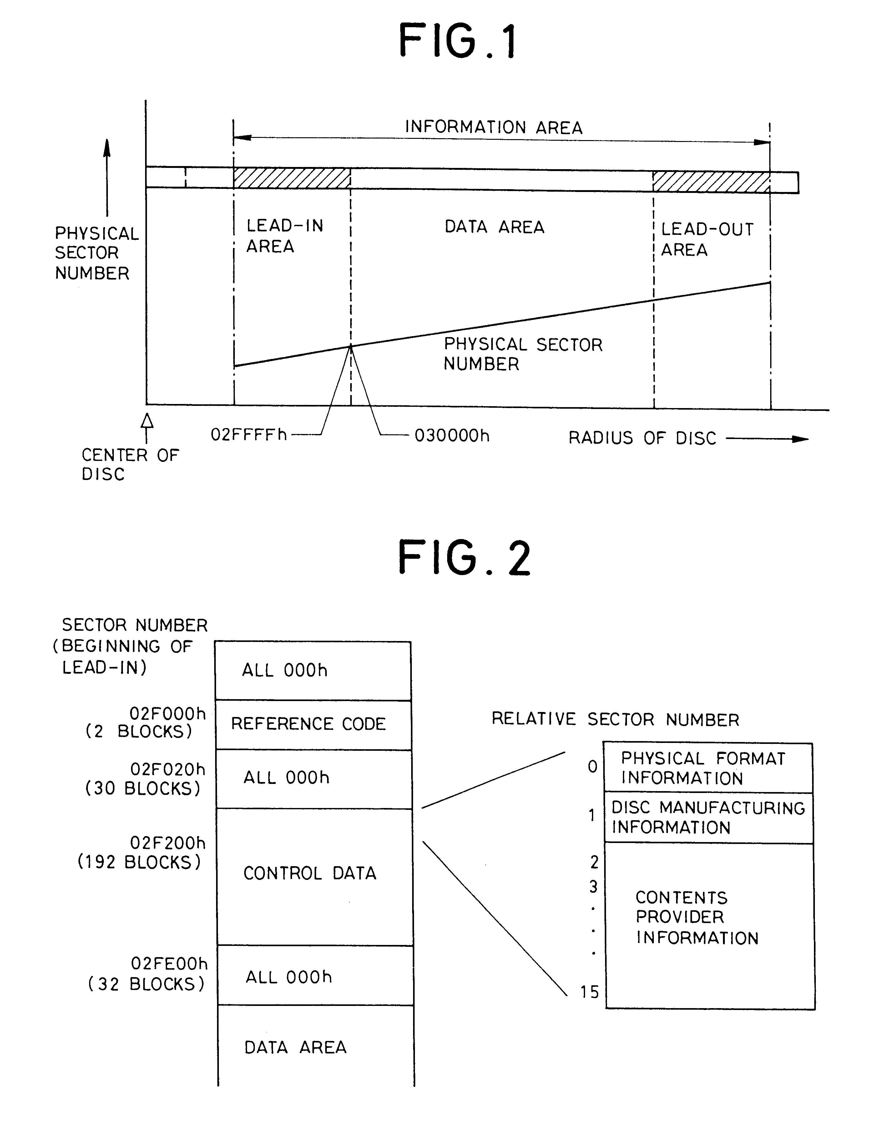
the present invention will be described in detail. FIG. 5 is a plan view schematically showing groove tracks 12 and land tracks 13 in a control data section in a lead-in area.

The groove tracks 12 are formed as intermittent groove tracks separated by portions of the same depth as the land tracks 13 (on the same plane), i.e., groove-absent portions, except for a neighborhood of a prepit train formed of three prepits 14A, 14B, 14C. The groove tracks 12 are created, for example, by 8 / 16 modulating a cutting light beam and turning ON / OFF the emitting power (with a duty ratio of approximately 50%) during the groove cutting. In other words, the groove tracks 12 have an intermittent structure, in which the groove tracks are divided based on a signal having the same frequency band as a recording RF signal (i.e., a recording signal after 8 / 16 modulated) recorded on the optical disc. It can be said that this structure is such that the lengths of each groove portion and groove-absent portion (h...

second embodiment

The second embodiment differs from the first embodiment in that a region adjacent to an entire area including prepits 14A, 14B, 14C is formed as a continuous mirror portion 22A on a track which is traced for reading the prepits 14A, 14B, 14C. More specifically, the mirror portion 22A is formed continuously at least from the leading end of the prepit 14A to the trailing end of the prepit 14C in the tracking direction. Also, in the second embodiment, another mirror portion 22B adjacent to the prepits 14A, 14B, 14C is formed opposite to the mirror portion 22A beyond the prepits 14A, 14B, 14C.

Thus, like the first embodiment, the foregoing structure prevents a reproduced RF signal from being read from the intermittent groove tracks in the recording region due to the interference of the intermittence of the groove tracks themselves with the recorded RF signal. On the other hand, pre-information can be read by the continuous mirror portions 22A, 22B in the regions adjacent to the prepits 1...

fourth embodiment

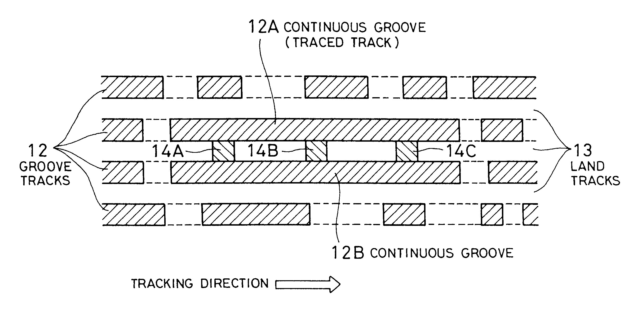
A third and the present invention will now be described with reference to FIGS. 7 and 8, respectively. FIGS. 7 and 8 are plan views schematically showing groove tracks 12 and land tracks 13 in a control data section in a lead-in area.

As can be seen from FIG. 7, the third embodiment differs from the aforementioned embodiments in that a continuous groove 12A adjacent to an entire area including at least prepits 14A, 14B, 14C is formed only on a track traced for reading the prepits 14A, 14B, 14C. Likewise, in this structure, pre-information can be read from this section since the interference of signals is avoided by the continuous groove 12A.

FIG. 8 in turn shows an example in which two prepits 14 are formed in sync frames other than the first one in a recording sector (i.e., prepits B2, B0 or prepits B2, B1). In the fourth embodiment, a continuous mirror portion 22A is formed instead of the continuous groove 12A, in which case similar effects to those of the foregoing third embodiment...


PUM


Abstract

At least a portion of groove tracks in a information-data recording region of an optical recording medium comprises a plurality of groove portions separated by groove-absent portions in a rotational direction of the optical recording medium, each of the mark portions or each of the space portions includes one of the groove-absent portions. At least one of two groove tracks adjacent to prepit train, which is formed in land tracks, has a continuous groove portion or a groove-absent portion extending at least from a leading end to a trailing end of at least one prepit included in the prepit train in a rotational direction of the optical recording medium. The frequency band for separation of the groove tracks includes at least a portion of a frequency band of a modulated recording signal for recording information data on the optical recording medium.

Description

1. Field of the InventionThe present invention relates generally to an optical recording medium and a manufacturing method thereof, and more particularly to a user recordable optical recording medium and a manufacturing method thereof wherein unauthorized recording and reproduction of information data is disabled.2. Description of the Related ArtAt present, a write-once DVD-R (Digital Versatile Disc-Recordable) has been commercially produced as a user recordable optical recording medium having a recording capacity of several gigabytes (Gbytes), and a rewritable DVD-RW (DVD-Rewritable) is under development. In addition, a large amount of high quality copies can be made without substantial degradation with the significantly improved performance of such large capacity digital optical recording media and recording / reproducing apparatus.FIG. 1 is a diagram showing a layout of a physical sector in a radial direction of a recording surface on a DVD-RW which is taken as an example. An infor...

Claims


Application Information

Patent Timeline
IPC IPC(8): G11B7/007G11B7/0037G11B7/00G11B20/12G11B7/26G11B7/24
CPCG11B7/007G11B7/00718G11B7/0037G11B20/1217G11B7/26G11B7/2407
Inventor MURAMATSU, EIJISUZUKI, TOSHIOKATO, MASAHIROTANIGUCHI, SHOJI
Owner PIONEER CORP
Why Eureka
Try Eureka