
Battery pack with improved heat radiation and sealing

a battery pack and heat radiation technology, applied in the field of battery packs, can solve the problems of increased manufacturing cost, leakage of electrolyte, shortening the service life of the cell,

Inactive Publication Date: 2003-03-25
MAKITA CORP
View PDF57 Cites 94 Cited by
  • Summary
  • Abstract
  • Description
  • Claims
  • Application Information

AI Technical Summary

Benefits of technology

Another object of the present invention is to provide a battery pack having a simple structure for improving the durability of the battery pack by lessening vibration and impact on the cells.
The above objects and other related objects are realized by the invention, which provides a battery pack comprising: a first case containing a plurality of battery cells; radiator means disposed in contact with the cells within the first case and having at least one surface for radiating heat conducted from the battery cells; a first air passage defined at least partially by said at least one surface of the radiator means and separated from the battery cells; and at least one air outlet formed in the first case and connected with the first air passage. This structure itself (i.e., not in cooperation with any other structure, such as a charger) easily prevents heat buildup in the battery cells in the battery pack and prevents entry of foreign matter into the inner case, thus prolonging the service life of the battery cells and preventing leakage of the electrolytic solution and short-circuiting due to rusting.
According to another aspect of the present invention, the battery cells are divided into a plurality of blocks and there is at least one second passage provided between the blocks, the at least one second air passage being in communication with the first air passage. The second air passage is provided between the cell blocks and cools the cells more evenly; thus more effectively preventing deterioration of the battery cells.
According to yet another aspect of the present invention, the battery pack further comprises a second case that is smaller than the first case, contains the battery cells and is disposed within the first case. Furthermore, the first air passage may be formed between the first and second cases and elastic material may be interposed between the first and second cases. The aforementioned double casing structure effectively lessens transmission of impact and vibration to the battery cells, thus enhancing the durability of the battery pack.

Problems solved by technology

In certain types of cells and batteries, such as nickel metal hydride cells, this phenomenon is so severe that the service life of the cells will be shortened unless some preventative measures are taken.
Although the foregoing structure can significantly lessen the deterioration of the battery cells by preventing heat buildup in the battery cells, it suffers from other drawbacks.
For example, moisture and other foreign matter can easily enter the battery pack through the openings in the battery pack and may rust the battery cells, which may cause leakage of the electrolyte.
Furthermore, conductive foreign matter may cause a short-circuit.
One significant drawback of this structure is an increase in the manufacturing cost due to the sliding doors and guide bosses protruding from the charger for opening and closing the doors.
Moreover, the existence of the guide bosses limits the types of battery packs that can be recharged on the charger, thus reducing its general versatility.
The durability and reliability of the mechanism for operating the sliding doors is somewhat questionable because the relatively fragile guide bosses may break when the battery pack is set on the charger.

Method used


Image

  • Battery pack with improved heat radiation and sealing
  • Battery pack with improved heat radiation and sealing
  • Battery pack with improved heat radiation and sealing

Examples


first embodiment

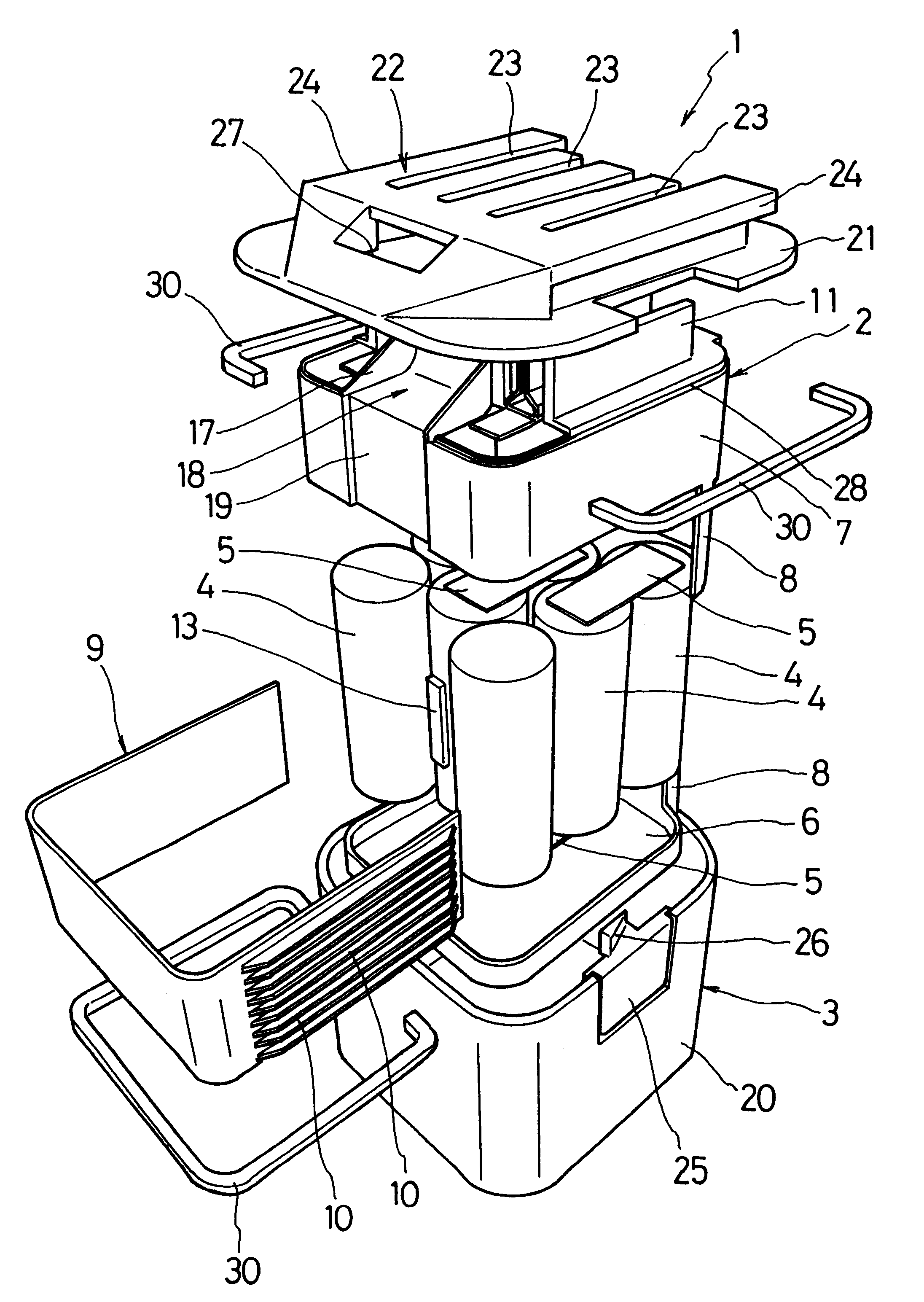
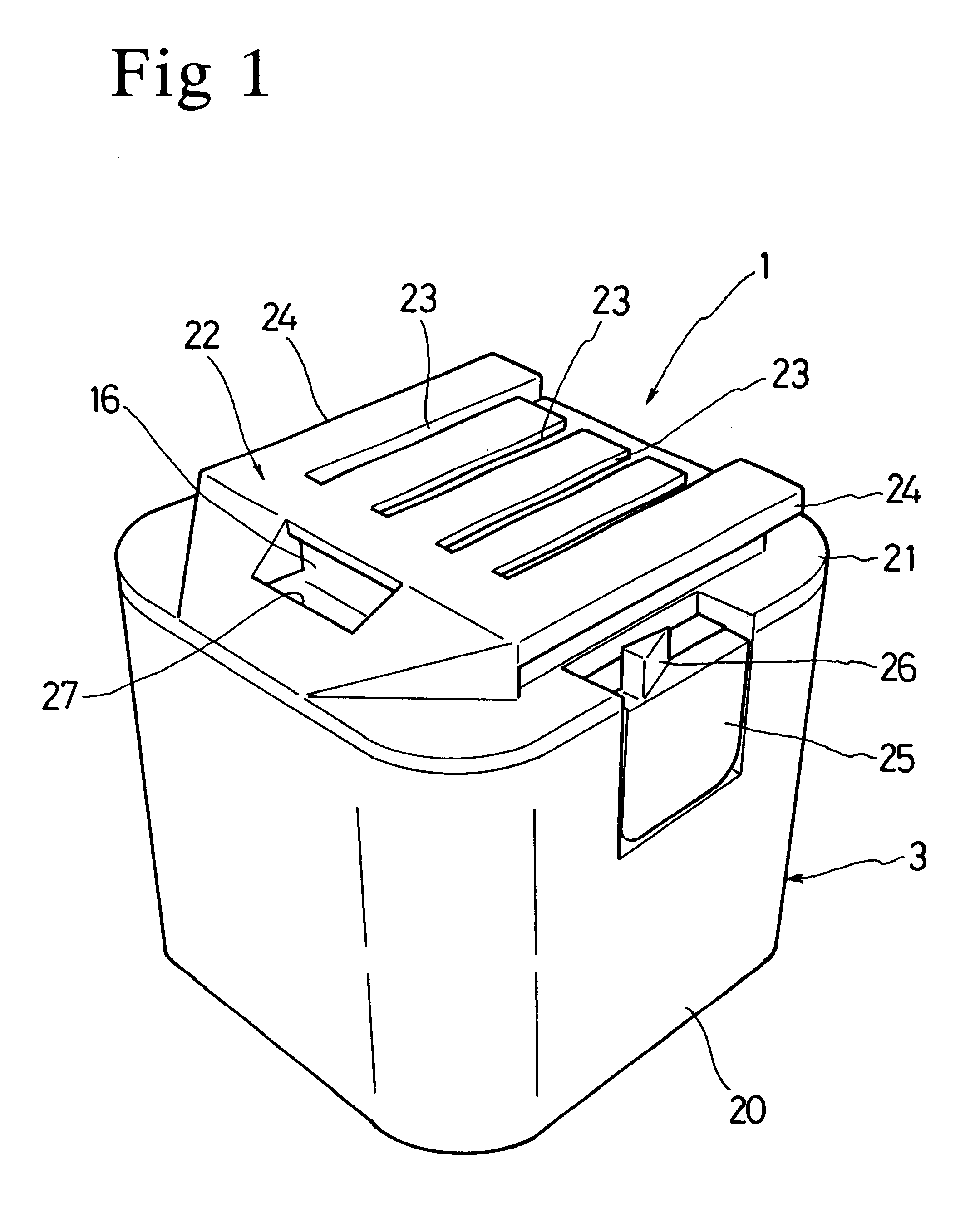
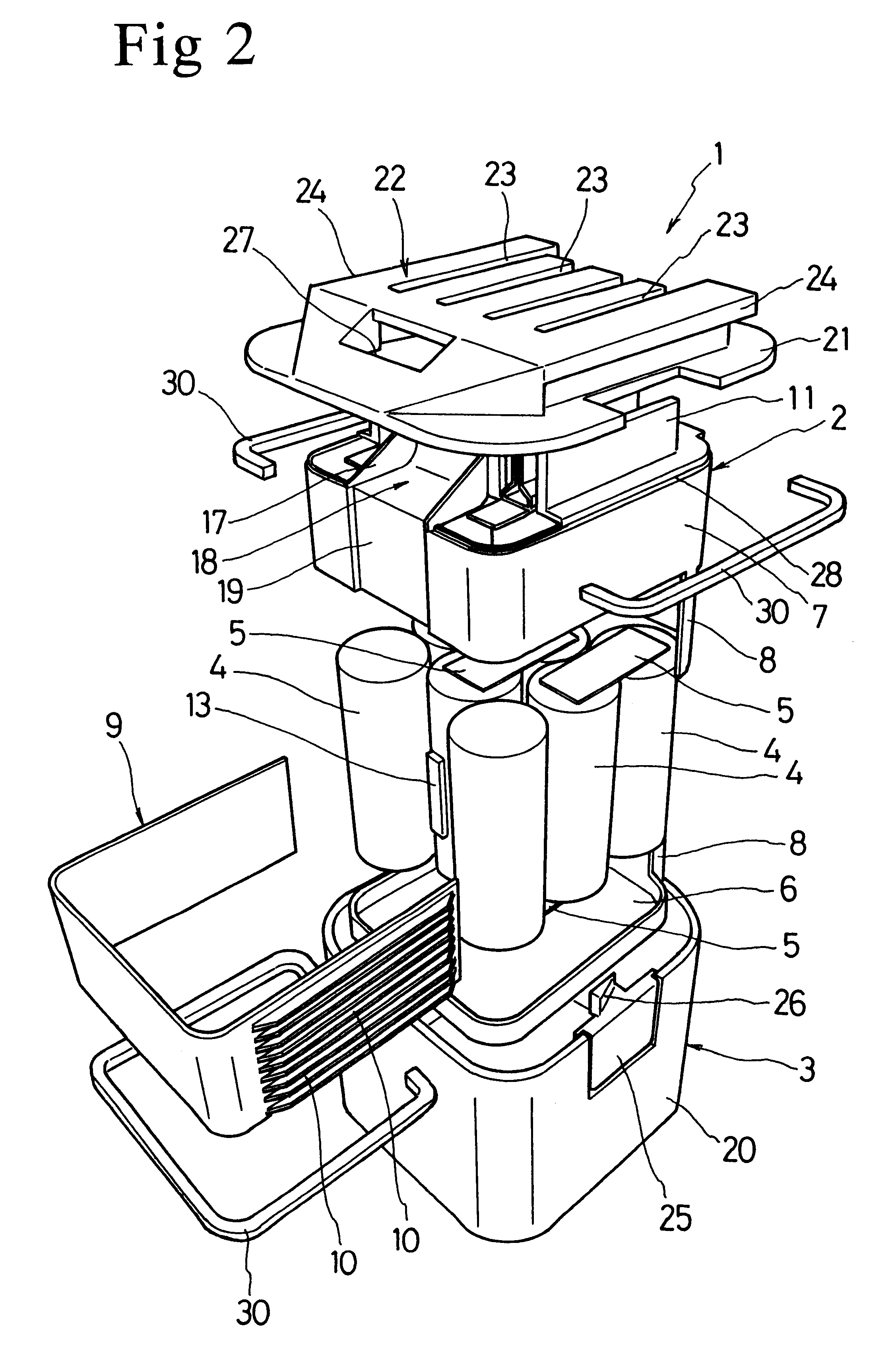
FIG. 1 is a perspective view of a battery pack I according to the present invention, and FIG. 2 shows an exploded view of the battery pack 1. The battery pack I has a double casing structure that includes a generally cubic inner case 2 for holding eight nickel metal hydride cells 4 in an upright position and a generally cubic outer case 3 for housing the inner case 2. The nickel metal hydride cells (hereinafter referred to as NiMH cells) 4 are connected in series by lead plates 5. The inner case 2 includes a base plate 6 on which the NiMH cells 4 are placed and a cover 7 disposed over the base plate 6. The inner case 2 further includes two coupling portions 8, each extending from the base plate 6 and the cover 7 for connecting the cover 7 to the base plate 6. The coupling portions 8 cover the side walls of the NiMH cells 4 located adjacent to the coupling portions 8, thus exposing the side walls of the other cells 4. Further included in the inner case 2 is an aluminum radiator plate...

second embodiment

In the structure of the first embodiment, if a large number of NiMH cells are contained within the inner case, some of the cells may not be disposed in contact with the radiator plate, thus failing to prevent heat buildup and deterioration of those cells. An alternate structure suitable for containing a large number of cells is described hereinafter with reference to FIGS. 7 and 8, in which identical or similar reference numerals or characters denote identical or similar parts or elements throughout the several views. Therefore, further description of such elements is omitted in order to avoid redundancy.

FIG. 7 is an exploded view of a battery pack 101 that includes an inner case 102 containing twenty-four NiMH cells 4, which are divided into two twelve-cell blocks 133. The battery pack 101 further includes two radiator plates 134 with ribs 135 that surround each block 133 of battery cells 4 so as to define between the blocks 133 a second air passage 136 connected to an air passage ...


PUM


Abstract

A battery pack (1) has a double casing structure, including an inner case (2) disposed inside an outer case (3). The inner case (2) includes a radiator plate (9) that is in contact with the side walls of battery cells (4) disposed within the battery pack (1). A forked air passage (32) extends from an air inlet (27) and is defined between the inner case (2) and the outer case (3) and along the outer surface of the radiator plate (9) until reaching a pair of air outlets (31).

Description

This application claims priority to Japanese Patent Application No. 10-294071 filed on Oct. 15, 1998 and Japanese Patent Application No. 11-78343, the contents of which are incorporated herein by reference.1. Field of the InventionThe present invention generally relates to battery packs. More particularly, the present invention relates to battery packs having battery cells that are disposed within a case and are used as power sources for electric power tools.2. Description of the Related ArtGenerally, battery packs for electric power tools include exposed electric terminals for charging and discharging the enclosed battery cells. When a battery pack is attached to an electric power tool, electrical contact is established between the terminals of the battery pack and the terminals of the battery holder in the tool, thus supplying power to the tool. When the charge level of a battery pack becomes low, the pack is set in a battery charger to establish electrical contact between the cha...

Claims


Application Information

Patent Timeline
IPC IPC(8): H01M2/10H01M10/50H01M10/42H01M10/46H01M10/60H01M10/613H01M10/6235H01M10/643H01M10/6551H01M10/6557H01M10/6563H01M50/213H01M50/253H01M50/296H02J7/00
CPCH01M2/1022H01M10/5004H01M10/5014H01M10/5073H01M10/5046H01M10/5059H01M10/5067H01M10/345H01M10/504H01M10/503H01M10/653H01M10/6563H01M10/6551H01M10/6557H01M10/643H01M10/6235H01M10/6566H01M10/613Y02E60/10H01M50/213H01M50/296H01M50/253
Inventor SUGIURA, MASATOSHIKATO, YOUICHISAKAKIBARA, KAZUYUKI
Owner MAKITA CORP
Learn More