Accumulator fuel injection system

a fuel injection system and accumulation technology, applied in mechanical equipment, machines/engines, electric control, etc., can solve the problems of oil dilution, oil dilution, seizure,

Inactive Publication Date: 2003-04-08
MITSUBISHI FUSO TRUCK AND BUS CORPORATION
View PDF6 Cites 18 Cited by
  • Summary
  • Abstract
  • Description
  • Claims
  • Application Information

AI Technical Summary

Benefits of technology

The additional injection of the low-pressure fuel prevents the fuel from adhering to the wall surfaces of the cylinder liners while keeping the fuel pressure as low as possible during the post injection. The post injection control device injects the additional fuel after the main injection control device injects the main fuel for a predetermined period of time, and this causes the additionally injected fuel to be combusted by flame in the combustion chamber or reacted in the exhaust passage to raise the exhaust temperature. The additional injection by the post injection control device (post injection) is implemented by fuel that has been reduced to a low pressure approximate to the pressure of the low-pressure fuel stored in the second accumulator.
Therefore, the penetration power of the injected fuel is suppressed during the post injection to prevent the fuel from adhering to the surface walls of the cylinder liners. This enables activation of an after treatment device provided in an exhaust system, for example, by raising the exhaust temperature while preventing oil dilution, seizure, and the like.

Problems solved by technology

However, it is not preferable to additionally provide the heat source as mentioned above since it complicates the arrangement of the after treatment system and increases the cost.
However, if high-pressure fuel is continuously injected during the post injection after fuel is injected at a high pressure, the fuel is adhered to the wall surfaces of cylinder liners to cause oil dilution, seizure, etc. due to the strong penetration power of the injected fuel.

Method used


Image

  • Accumulator fuel injection system
  • Accumulator fuel injection system
  • Accumulator fuel injection system

Examples


Embodiment Construction

A preferred embodiment of the present invention will now be described in detail with reference to the accompanying drawings.

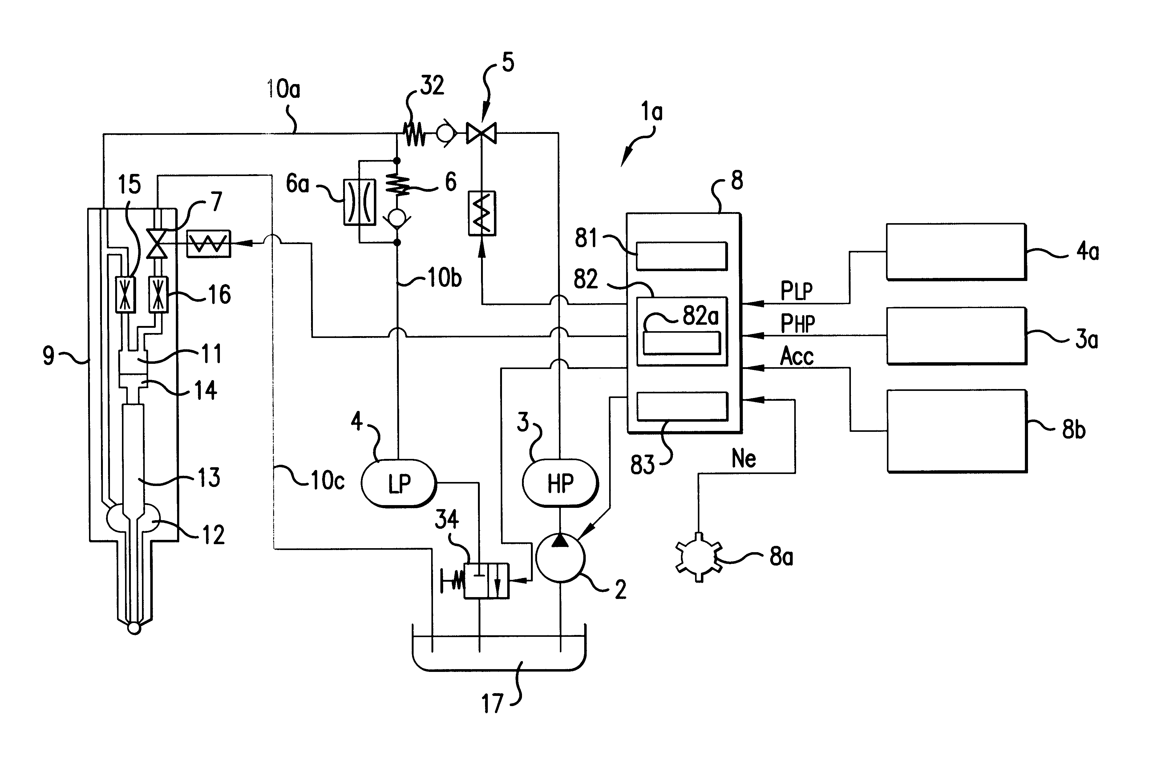
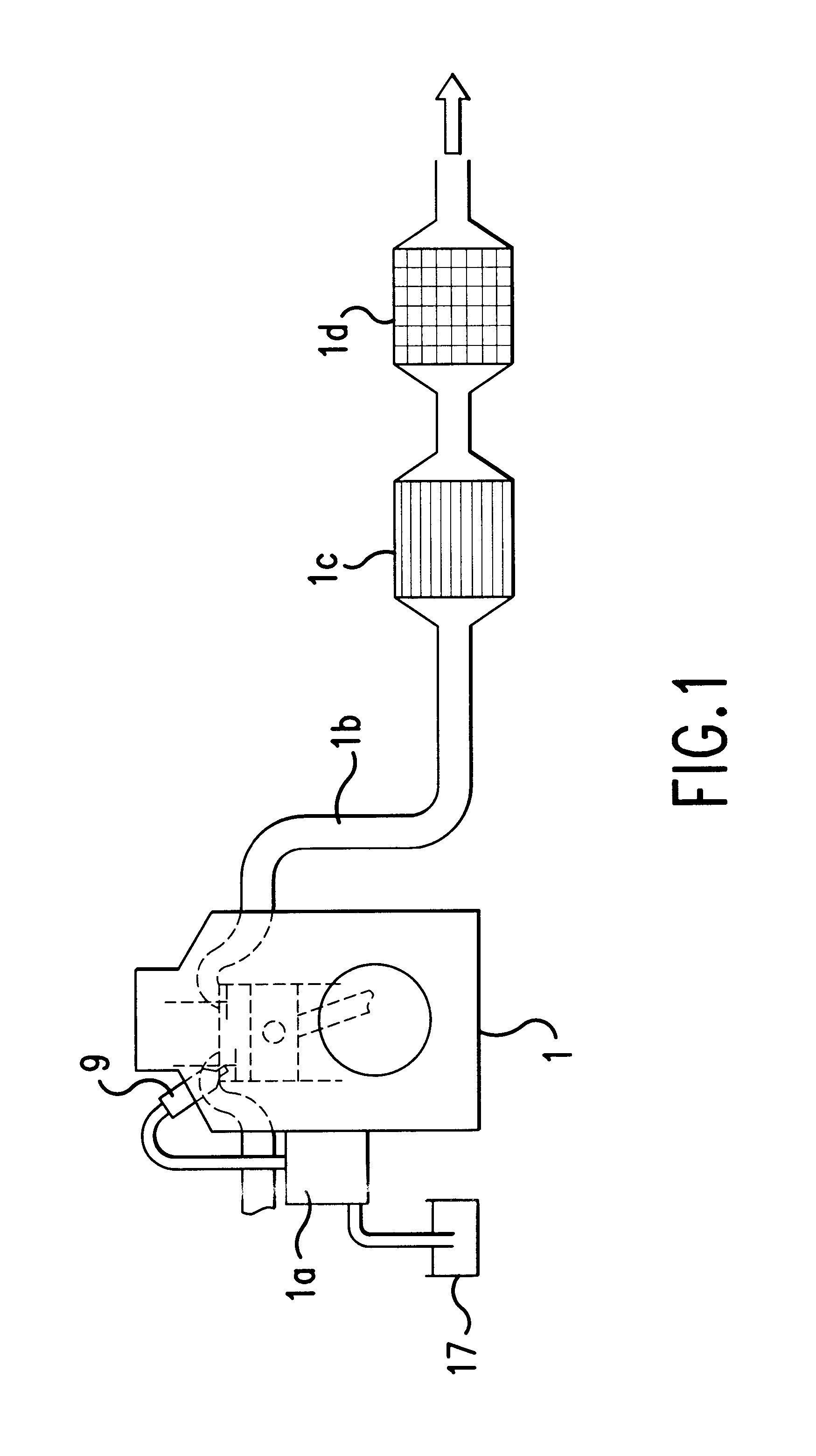
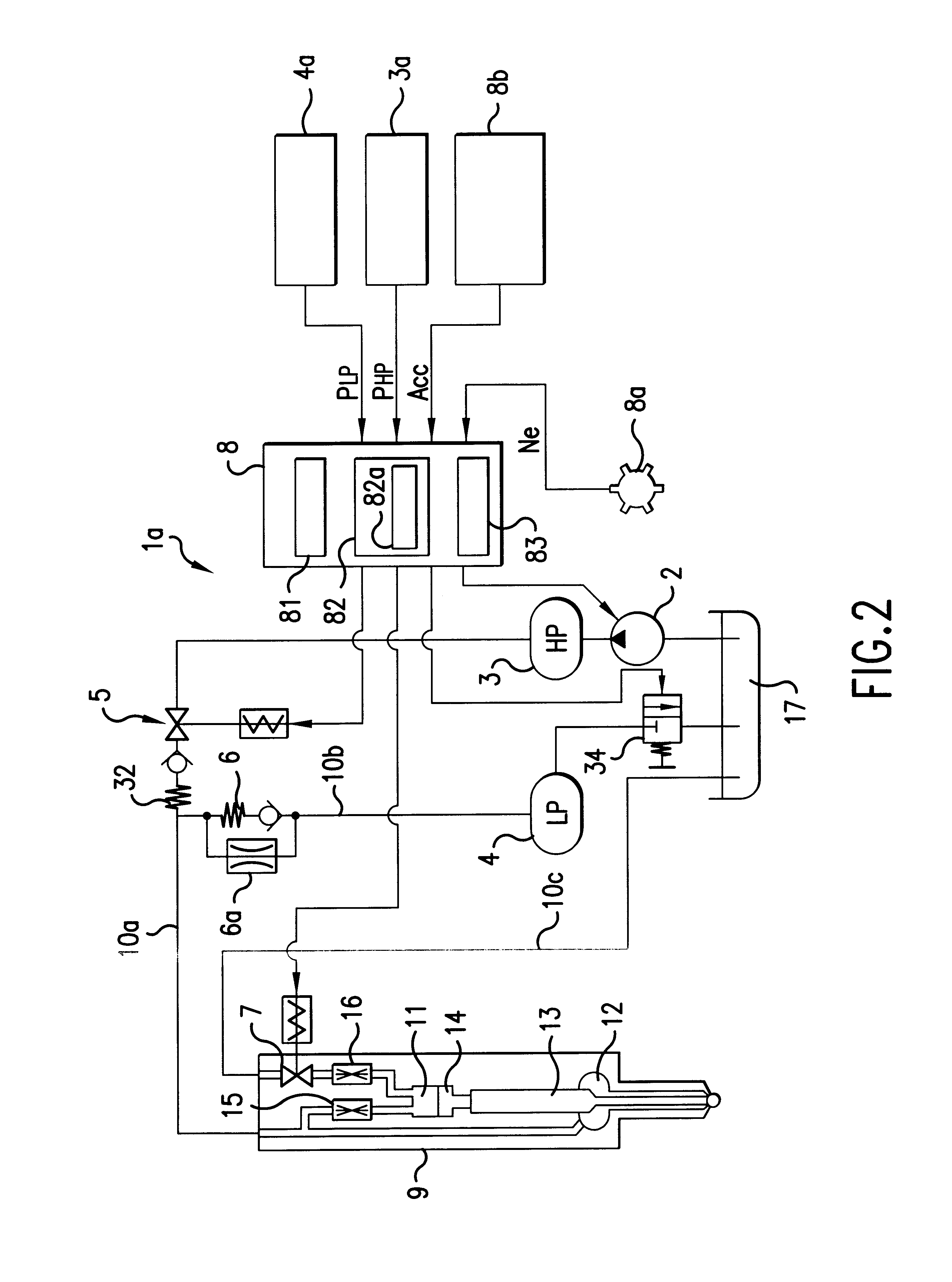
FIG. 1 shows a diesel engine 1 to which is applied an accumulator fuel injection system 1a according to the present invention, and FIG. 2 shows the arrangement of the accumulator fuel injection system 1a according to the present invention.

As shown in FIG. 1, the diesel engine 1 is a serial four cylinder diesel engine, for example, and an after treatment device is provided in an exhaust passage 1b of the engine 1. The after treatment device is constructed such that an oxidization catalyst 1c is provided upstream a diesel particulate filter 1d. Such an after treatment device in which the oxidization catalyst is provided upstream the diesel particulate filter is called a continuous regenerative diesel particulate filter that is capable of continuously removing particulate matters deposited thereon by supplying an oxidization agent (NO.sub.2) generated by the oxidi...


PUM


Abstract

In a common rail system comprised of a first accumulator storing high-pressure fuel and a second accumulator storing low-pressure fuel, additional fuel is injected when a fuel pressure in a fuel passage or in the second accumulator (low inlet pressure of an injector) is reduced to a low pressure approximate to the pressure of the low-pressure fuel stored in the second accumulator after a switching valve is operated for disconnection from the fuel passage (switching valve drive signal OFF) at a point in time when a main injection control device finishes the injection of fuel (injector drive signal OFF) or after the main injection control device finishes the injection of fuel. This keeps the fuel pressure as low as possible during post injection to prevent the fuel from adhering to the wall surfaces of cylinder liners.

Description

This non-provisional application claims priority under 35 U.S.C. .sctn.119(a) on Patent Application No. 2001-107478 filed in Japan on Apr. 5, 2001, which is herein incorporated by reference.1. Field of the InventionThis invention relates to an accumulator fuel injection system, and more particularly to an accumulator fuel injection technique for quickly activating an exhaust emission control device in a diesel engine.2. Description of Related ArtExhaust gases emitted from a diesel engine installed in a bus, truck, or the like include a lot of particulate matters as well as HC, CO, NOx, etc. Accordingly, a diesel particulate filter that takes hold of particulate matters and removes them by burning with an external heat source, and an oxidization catalyst that processes HC and CO have been developed as after treatment devices for diesel engines. Recently, a continuous regenerative diesel particulate filter has also been proposed in which instead of an external heat source that burns p...

Claims


Application Information

Patent Timeline
Patent Type & Authority Patents(United States)
IPC IPC(8): F02D41/38F02D41/40F02M45/00F02M47/02F02M45/02F01N7/00F01N7/02F02B3/06F02B3/00F02M45/04F01N13/02F02D41/04F02M47/00F02M55/02
CPCF02D41/3836F02D41/405F01N13/009F02M45/02F02M47/027F01N2250/02F02B3/06F02D41/3854F02D2041/3881F02D2200/0602F02D2200/602F02D2250/31Y02T10/44F02D2041/389Y02T10/40F02M47/00
Inventor KOHKETSU, SUSUMUTANABE, KEIKINAKAYAMA, SHINJI
Owner MITSUBISHI FUSO TRUCK AND BUS CORPORATION
Why Eureka
Try Eureka