
Illumination device having an inverter and an igniter disposed in a lamp body

a technology of inverter and igniter, which is applied in the field of illumination devices, can solve problems such as deterioration of startability, and achieve the effect of reducing the length of such parts and excellent startability

Inactive Publication Date: 2003-04-22
MATSUSHITA ELECTRIC WORKS LTD
View PDF12 Cites 16 Cited by
  • Summary
  • Abstract
  • Description
  • Claims
  • Application Information

AI Technical Summary

Benefits of technology

The present invention is to overcome the foregoing problems, and its object is to provide a luminaire which can reduce the length of such part to which the high voltage is applied as the harness employed in the lighting circuit, and which can attain an excellent startability.

Problems solved by technology

In the conventional luminaire as in the above, however, there have been problems that, since in general the socket and igniter in the lighting device are connected through a harness, parts of a high withstand-voltage are required when a high voltage is applied to the harness, the startability is deteriorated, and so on.

Method used


Image

  • Illumination device having an inverter and an igniter disposed in a lamp body
  • Illumination device having an inverter and an igniter disposed in a lamp body
  • Illumination device having an inverter and an igniter disposed in a lamp body

Examples


Embodiment Construction

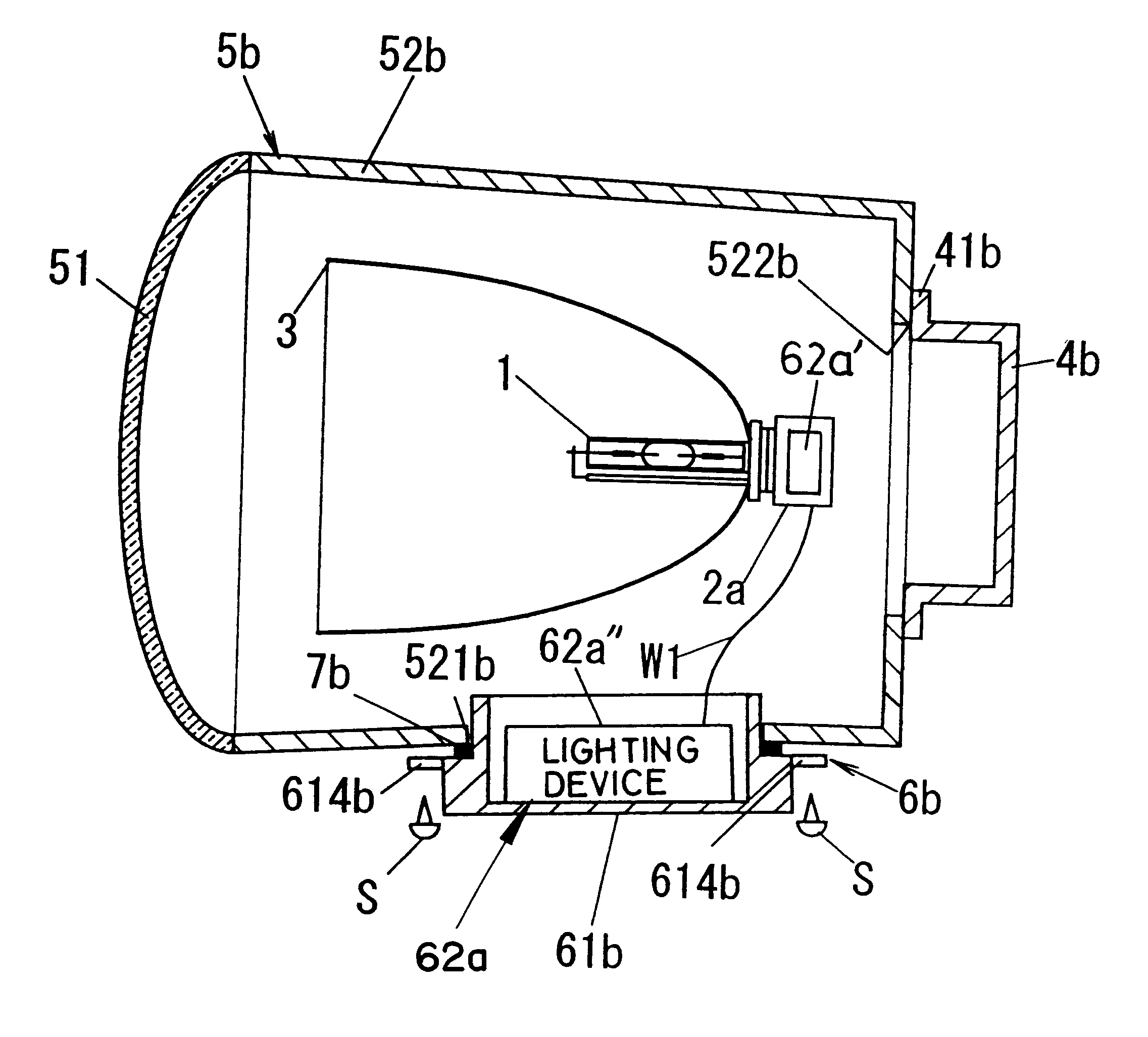
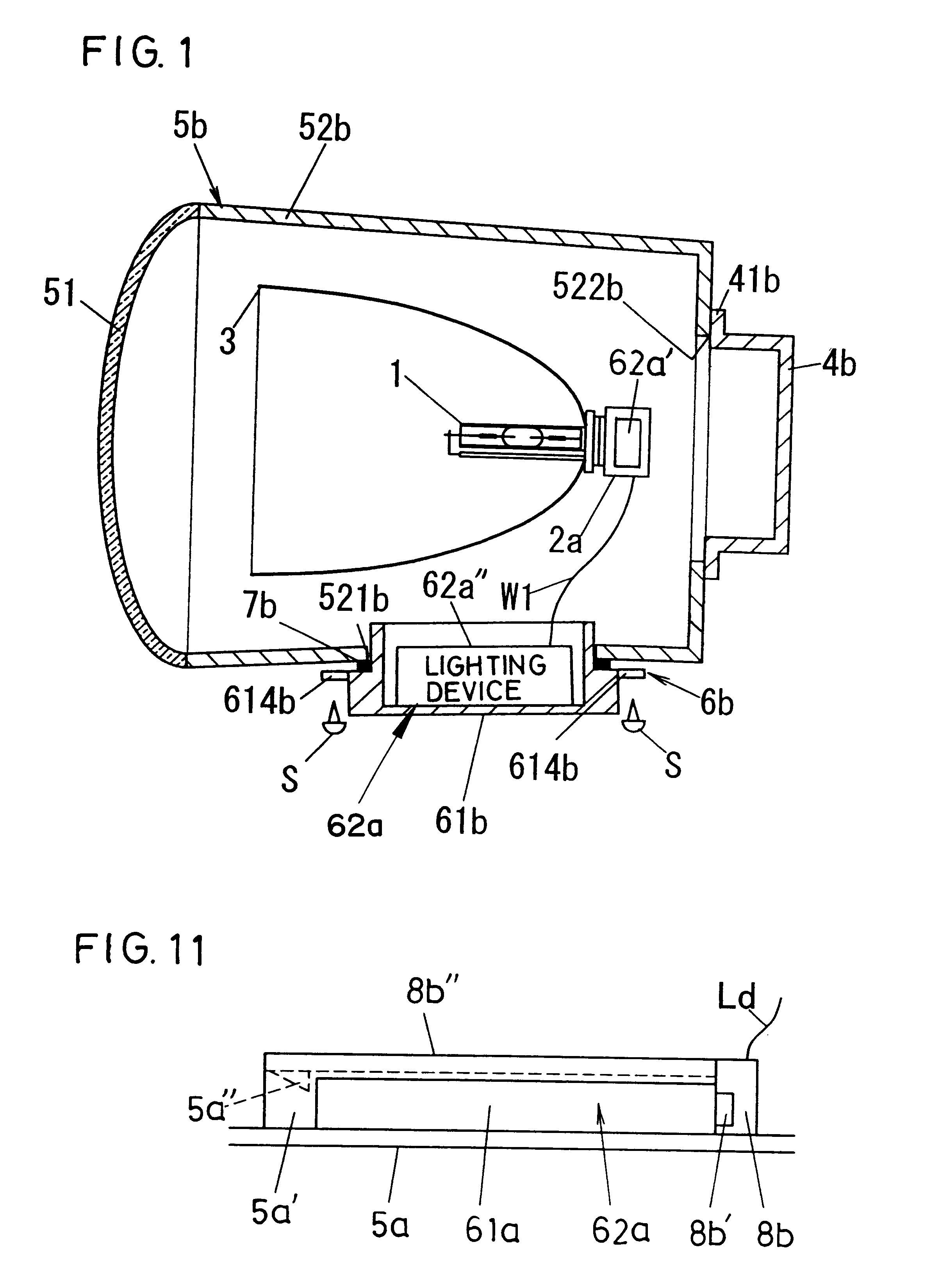
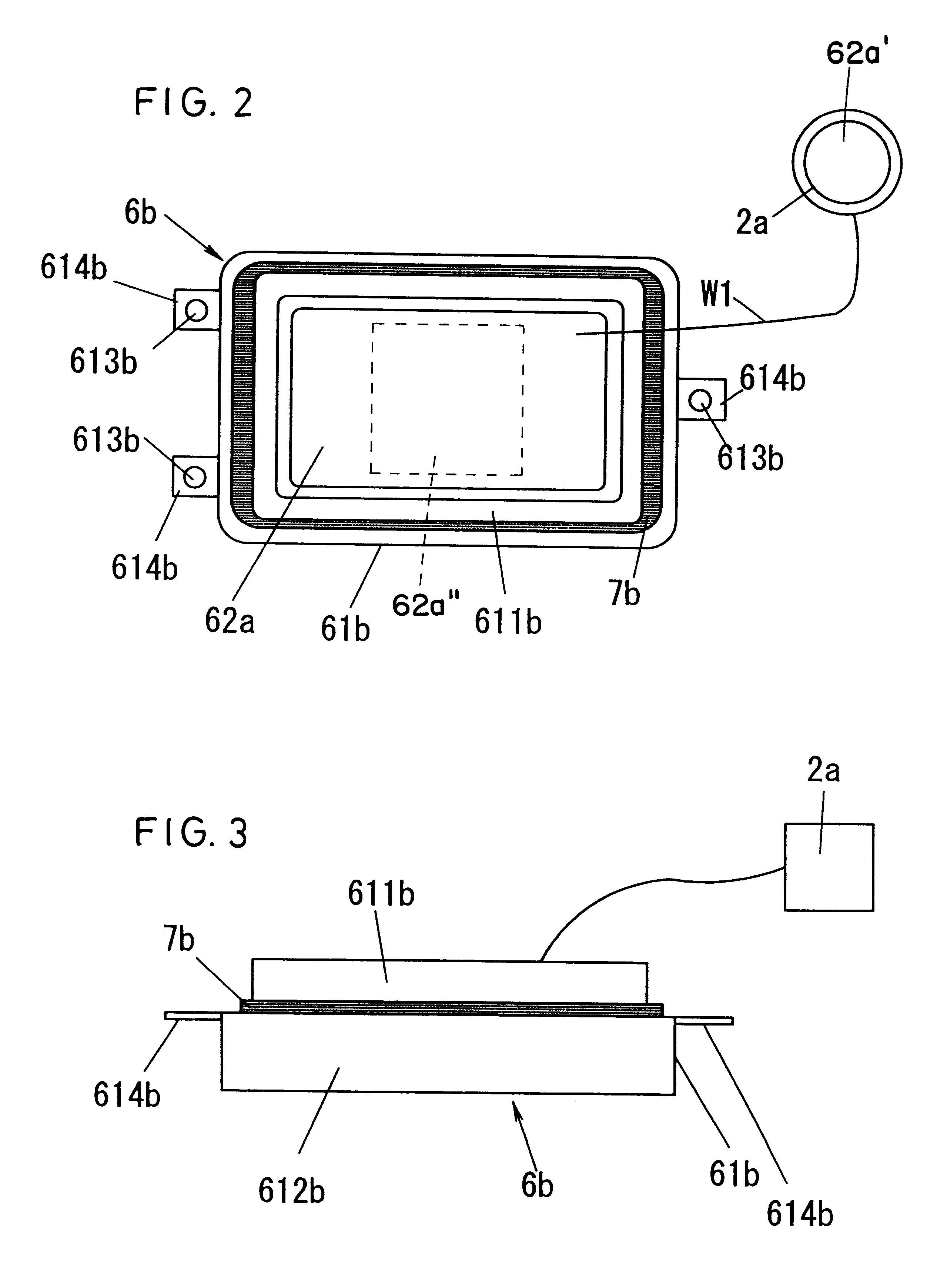
The luminaire in an embodiment of the present invention as shown in FIGS. 1-3 may be used as an automotive head lamp, which comprises[, in concrete,] such discharge lamp 1 as a metal halide lamp, a lamp socket 2a formed in a bottomed cylindrical shape, i.e., closed at one end, and capable of mounting a rear (righthand in the drawings) electrode section of the discharge lamp 1. The lamp socket 2a has connecting terminals for electrical connection to respective electrodes of the discharge lamp 1 and, preferably, is provided with an igniter 62a'. The luminaire further includes a reflector 3 which is a concave mirror (mirror of paraboloid of revolution in the drawings) for reflecting luminous light of the discharge lamp 1 forward (leftward in the drawing) and having a hole at the rearmost part for inserting the discharge lamp 1 into the concave mirror, and a lamp cover 4b for mounting and exchanging the discharge lamp 1 and formed in a box shape opened on its front face (including a bot...


PUM


Abstract

A luminaire includes a discharge lamp, a lighting device supplying a power for lighting the discharge lamp, and a lamp body for housing the discharge lamp and an igniter for starting the discharge lamp, the lighting device and igniter being provided separately, while the lighting device being disposed in the lamp body, whereby such parts employed in the lighting device as harness or the like to which a high voltage is applied can be shortened in the length to be able to improve the safety.

Description

TECHNICAL FIELDThis invention relates to luminaires, for example, a luminaire employed in automotive head lamp.BACKGROUND OF THE INVENTIONThe luminaires employed in the automotive head lamps have been disclosed in Japanese Patent Laid-Open Publications Nos. 7-57503 and 10-147174, Japanese Patent No. 2,761,132, U.S. Pat. No. 6,066,921 and so on. In particular, U.S. Pat. No. 6,066,921 has been assigned to the same assignee as the assignee of the present application, and its luminaire comprises a lamp including a discharge lamp, socket, reflector, lamp cover, lens and lamp body, a lighting device including an inverter and igniter, and a coupler, wherein the socket connected through cables to the lighting device inserted in the lamp.In the conventional luminaire as in the above, however, there have been problems that, since in general the socket and igniter in the lighting device are connected through a harness, parts of a high withstand-voltage are required when a high voltage is appli...

Claims


Application Information

Patent Timeline
Patent Type & Authority Patents(United States)
IPC IPC(8): F21V31/00F21S8/10F21V19/00F21V17/00F21V23/02F21V23/00H05B41/04H05B41/28H05B41/00H05B41/292
CPCB60Q1/007B60Q1/0094F21S48/1109F21S48/1186H05B41/2921F21V23/026F21V31/00H05B41/00H05B41/042F21V23/00F21S48/155F21W2101/10F21S41/172F21S41/192F21S41/55F21W2102/00
Inventor UENO, MASATOSHIKATAOKA, HISAO
Owner MATSUSHITA ELECTRIC WORKS LTD
Learn More