Wheel bearing with positive-locking connection

a positive-locking connection and bearing technology, applied in the direction of mechanical equipment, transportation and packaging, couplings, etc., can solve the problems of increased wear, increased friction, and unnecessary heating so as to avoid the constraining force of the constant velocity joint and the effect of simple production

Inactive Publication Date: 2003-04-22
SCHAEFFLER KG
View PDF6 Cites 9 Cited by
  • Summary
  • Abstract
  • Description
  • Claims
  • Application Information

AI Technical Summary

Benefits of technology

The object of the invention is to provide a novel connection between the wheel bearing and the constant velocity joint, which connection meets the requirements for lightweight construction, is simple to produce and avoids constraining forces in the constant velocity joint.

Problems solved by technology

There are problems with this design.
A further problem is that the tooth system extends over the entire axial length of the constant velocity joint.
These constraining forces lead to additional undesirable heating in the constant velocity joint and to increased wear.

Method used


Image

  • Wheel bearing with positive-locking connection
  • Wheel bearing with positive-locking connection
  • Wheel bearing with positive-locking connection

Examples


Embodiment Construction

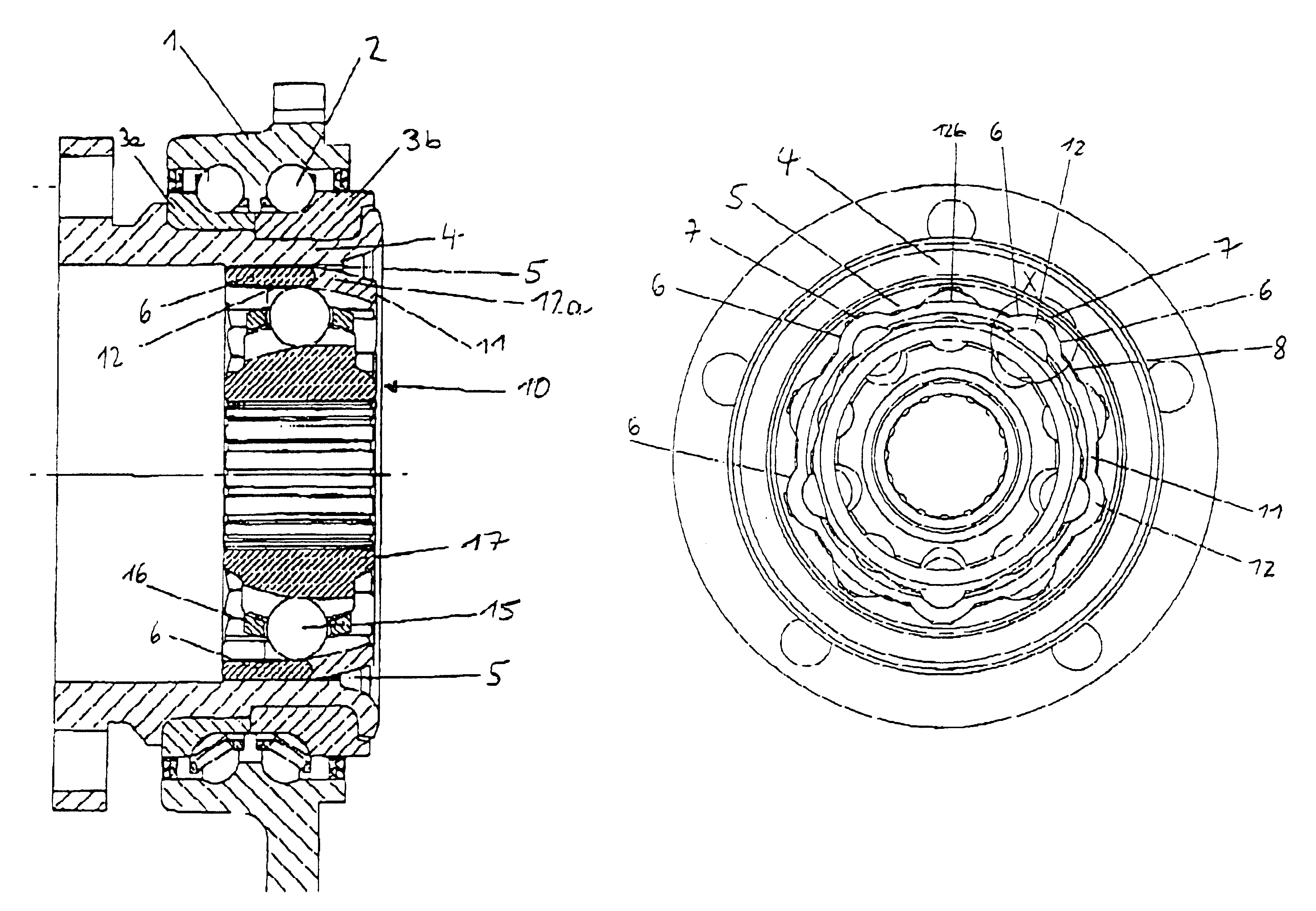
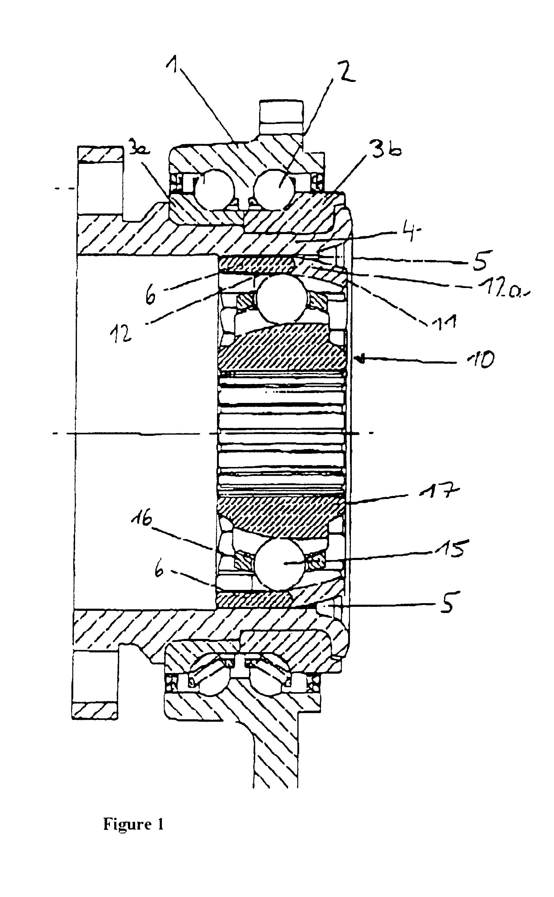
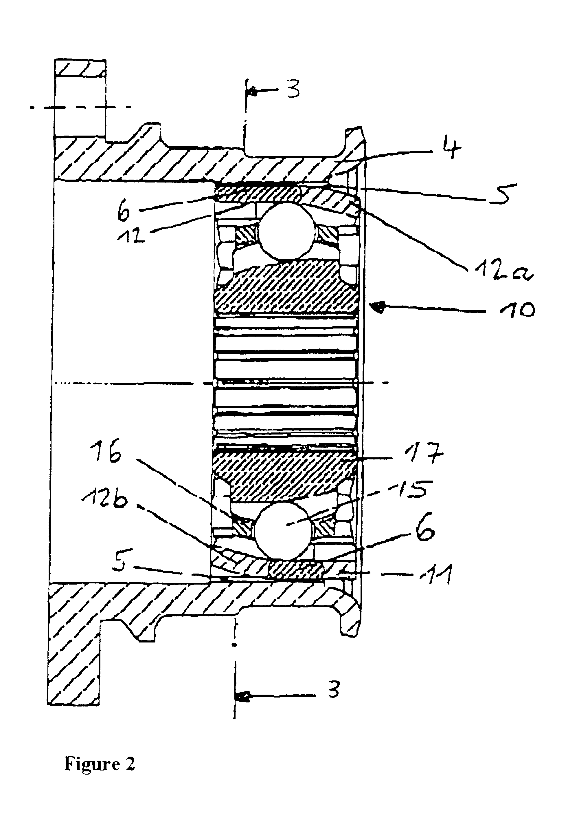
A constant velocity joint is located inside the inner ring flange of the wheel bearing around the joint. According to the invention, there is a tooth system inside the inner ring flange of the outer surrounding wheel bearing, to which the torque is transmitted. The teeth of the tooth system extend axially across the inner ring flange, and have circumferentially leading and trailing tooth flanks. The tooth system is designed to mesh with the generally complementary contours of the sheet-metal outer ring of the constant velocity joint in defined sections so that those elements rotate together. These contours of the outer ring of the joint are obtained during the sheet-metal working. The tooth system does not come in contact in the end region of the track running radially inward.

There are surprising advantages of this tooth system located in the inner ring flange.

The outer contour of the outer ring of the constant velocity joint, which contour is obtained during the sheet-metal working...


PUM


Abstract

A wheel bearing with an integrated constant velocity joint. The joint has a sheet-metal outer ring. Drive torque is transmitted from the outer ring of the constant velocity joint to the inner ring flange of a surrounding bearing by a tooth system. The tooth system is formed in the inner ring flange in such a way that it supports a wavelike outer contour of the outer ring of the constant velocity joint over a defined circumferential length section of the outer ring. The outer ring of the joint has tracks that mesh with the tooth system. The ends of the tracks are bent inward away from the tooth system.

Description

The invention relates to a wheel bearing and a constant velocity joint, wherein the outer ring of the constant velocity joint is connected to the inner ring flange of the wheel bearing via a positive-locking connection to transmit torque from the constant velocity joint to the wheel bearing via this positive-locking connection.Integration of parts and an associated demand for lightweight construction are long known requirements in automobile construction. This also applies to the wheel bearing arrangement and to the attempt to integrate as many functions as possible into the wheel bearing arrangement from its surroundings.Intensive effort has been made in integrating a constant velocity joint into a wheel bearing. A construction unit comprising a constant velocity joint and a wheel bearing is shown in DE 23 29 554 A1. The constant velocity joint is of a solid type of construction and is connected directly to the inner ring flange via a splined shaft profile. There are problems with ...

Claims


Application Information

Patent Timeline
Patent Type & Authority Patents(United States)
IPC IPC(8): B60B27/00F16D3/16F16D3/224B60B35/18B60B35/14F16C19/18F16D3/20F16D3/2237
CPCB60B27/0005B60B27/0026B60B27/0042B60B27/0084F16D3/224F16D3/2237Y10S464/906F16D2003/22306F16D2003/22309F16D2003/22326
Inventor HOFMANN, HEINRICHNIEBLING, PETERKLEINMANN, PETER
Owner SCHAEFFLER KG
Why Eureka
Try Eureka