

Production method for continuous casting cast billet
a production method and technology of casting billet, applied in casting apparatus, manufacturing tools, melt holding vessels, etc., can solve the problems of reducing the yield of a product, difficult to manufacture cast pieces stably in the method, and malfunction in production, and achieve the effect of increasing the cost of equipmen
- Summary
- Abstract
- Description
- Claims
- Application Information
AI Technical Summary
Benefits of technology
Problems solved by technology
Method used
Image

Examples
example 1
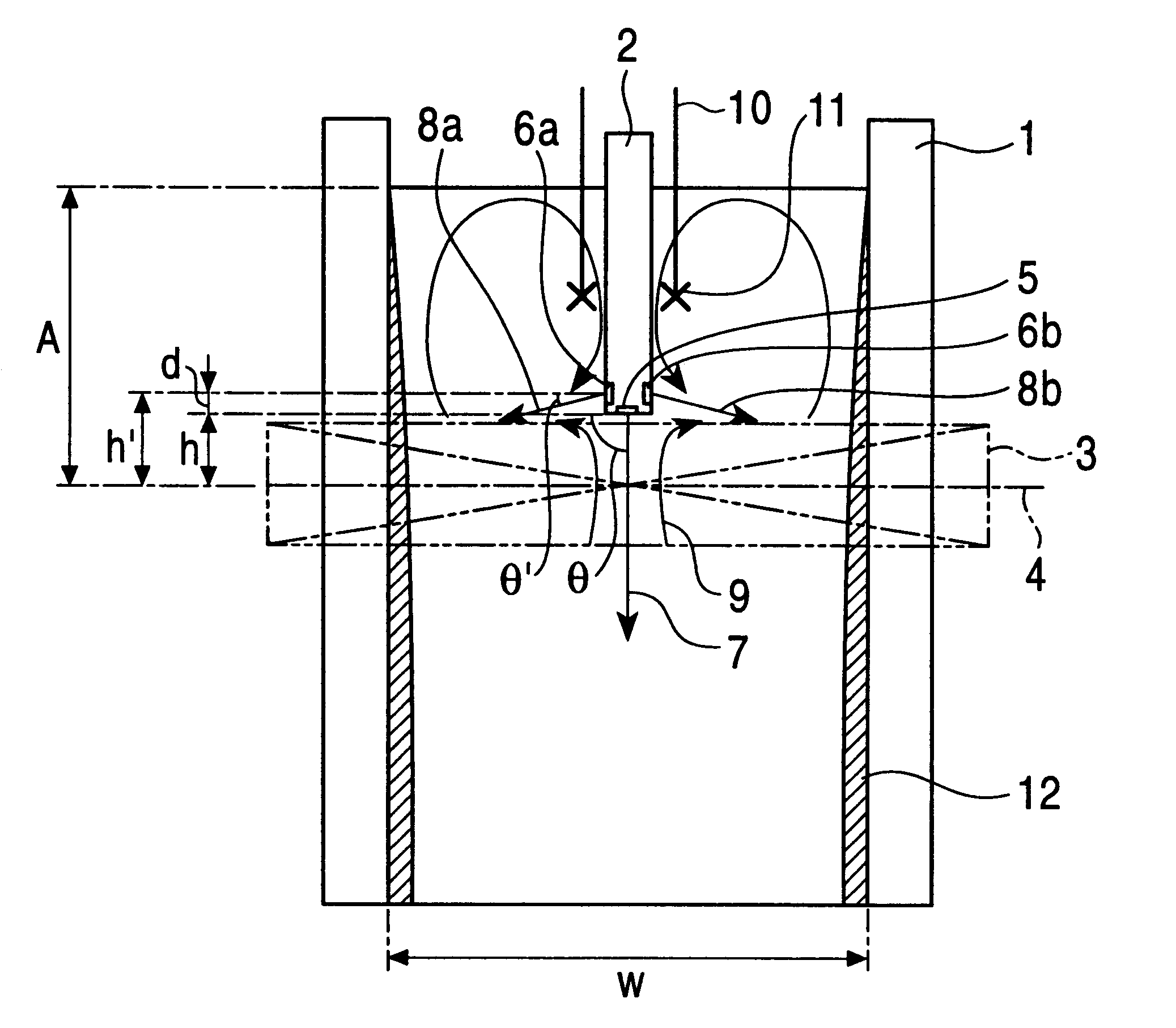
Direct current magnetic field application position (distance from molten metal level in mold to center of height of magnetic pole)
A: 0.347 m
Strength of applied magnetic field: 0.3 T
Height of magnetic field: 0.15 m
Immersion nozzle
Upper ejection hole: 2 holes, size of hole 10*10 mm
ejection angle .theta.=0.degree. (horizontal)
Lower ejection hole: single hole, size of hole 28 mm
dia (circle)
ejection angle .theta.=90.degree. (vertically downward)
Immersed depth of lower hole (from molten metal level in mold to lower end of lower ejection hole) 0.34 m
Immersed depth of upper holes (from molten metal level in mold to center of upper ejection hole) 0.177 m
Inner diameter of immersion nozzle 0.040 m
Distance from lower ejection hole to center of height of magnetic pole h: 0.007 m
Distance from upper ejection hole to center of height of magnetic pole h': 0.170 m
Casting speed: 1.6 m / min Throughput of cast: 0.49 t / min
Supply rate of molten steel from upper holes Q':
Q'=0.76 Q (0.76 times consumption ra...
example 2
Direct current magnetic field application position (distance from molten metal level in mold to center of height of magnetic pole)
A: 0.347 m
Strength of applied magnetic field: 0.3 T
Immersion nozzle
Upper ejection hole: 2 holes, size of hole 10*10 mm
ejection angle .theta.=0.degree. (horizontal)
Lower ejection hole: single hole, size of hole 28 mm
dia (circle)
ejection angle .theta.=90.degree. (vertically downward)
Immersed depth of lower hole (from molten metal level in mold to lower end of lower ejection hole) 0.290 m
Immersed depth of upper hole (from molten metal level in mold to center of upper ejection hole) 0.127 m
Inner diameter of immersion nozzle 0.040 m (40 mm)
Distance from lower ejection hole to center of height of magnetic pole h: 0.057 m
Distance from upper ejection hole to center of height of magnetic pole h': 0.220 m
Casting speed: 1.2 m / min Throughput of cast: 0.37 t / min
Supply rate of molten steel from upper holes Q':
Q'=0.63 Q (0.63 times consumption rate of molten steel that ...
example 3
Dimension of mold: long side 1.2 m, short side=0.26 m, height=0.9 m
Direct current magnetic field application position (distance from molten metal level in mold to center of height of magnetic pole) A: 0.60 m
Height of magnetic pole: 0.2 m
Strength of applied magnetic field: 0.3 T
Immersion nozzle
nozzle inside diameter: 90 mm
upper hole: 2 holes,
size of hole 21*30
lower hole: 2 holes, size of hole 49 mm dia (circle)
Distance from lower ejection hole to center of height of magnetic pole h: 0.10 m
Distance from upper ejection hole to center of height of magnetic pole h': 0.30 m (d=0.2 m)
Casting speed: 1.6 m / min
Throughput of cast: 3.5 t / min
Supply rate of molten steel from upper holes Q':
PUM
| Property | Measurement | Unit |
|---|---|---|
| magnetic field | aaaaa | aaaaa |
| width | aaaaa | aaaaa |
| size | aaaaa | aaaaa |
Abstract
Description
Claims
Application Information