Automated soldering system

a soldering system and automatic technology, applied in the direction of ohmic-resistance heating, manufacturing tools, solventing apparatus, etc., can solve the problems of not optimizing the functionality of the different cartridge tips available in the market, new technologies encountered serious shortcomings, and solventing stations

Inactive Publication Date: 2003-05-13
HAKKO CO LTD
View PDF12 Cites 66 Cited by
  • Summary
  • Abstract
  • Description
  • Claims
  • Application Information

AI Technical Summary

Problems solved by technology

Therefore. traditional soldering stations, which had only one power output level, did not optimize the functionality of the different cartridge tips available in the market.
However, even these new technologies encountered serious shortcomings.
As a result, the sensed temperature of the heating element within the cartridge did not reflect the true temperature of the tip.
Second, because of the distance between the sensor and the tip, the temperature gradient between the sensor and the tip could often be steep.
Although the user skill level required to measure and to calculate the difference was certainly lower than that required to adjust the dials, the process still expended valuable time.
A mo

Method used


Image

  • Automated soldering system
  • Automated soldering system
  • Automated soldering system

Examples


Embodiment Construction

will be made with reference to the accompanying drawings wherein:

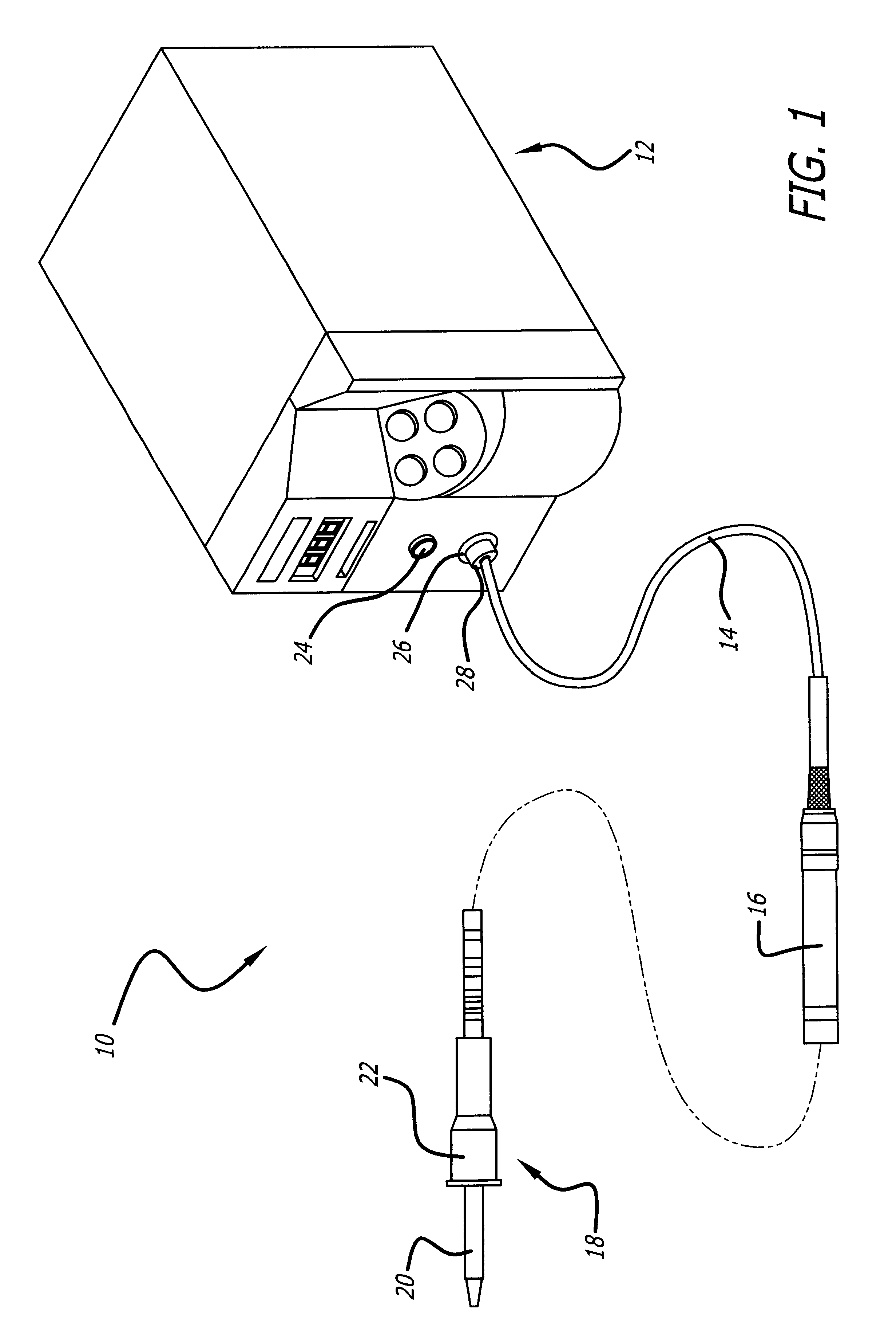
FIG. 1 shows a perspective view of the soldering system including a cartridge assembly, power supply, a reader and a power cable coupling the cartridge to the power supply;

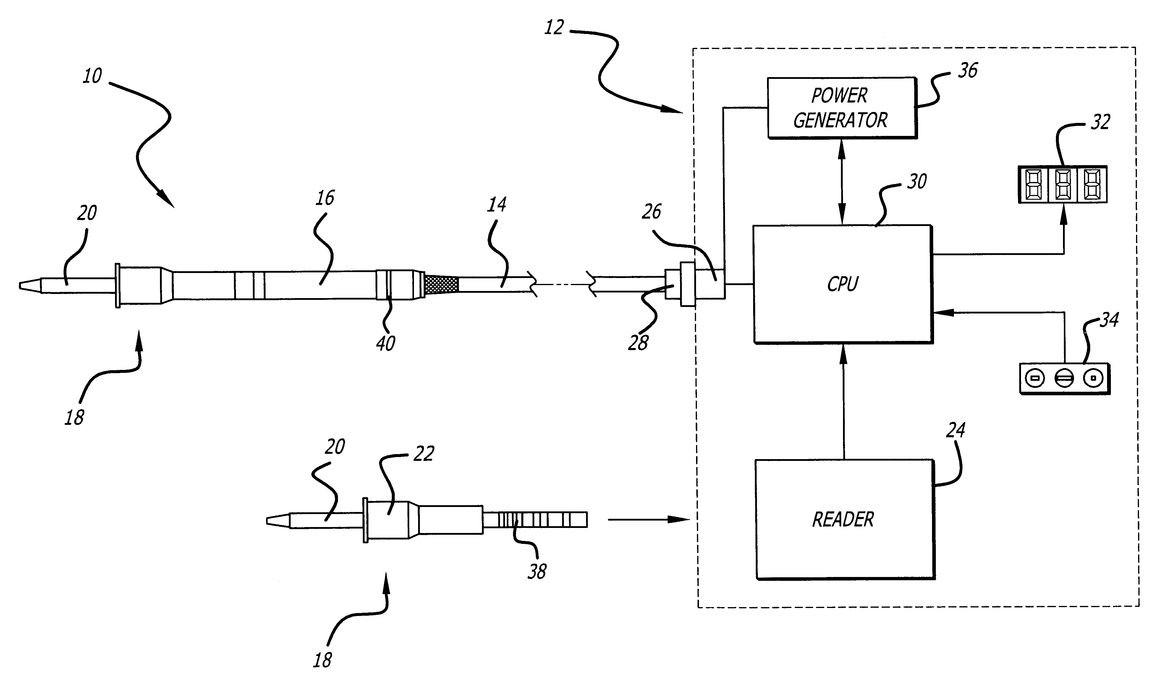
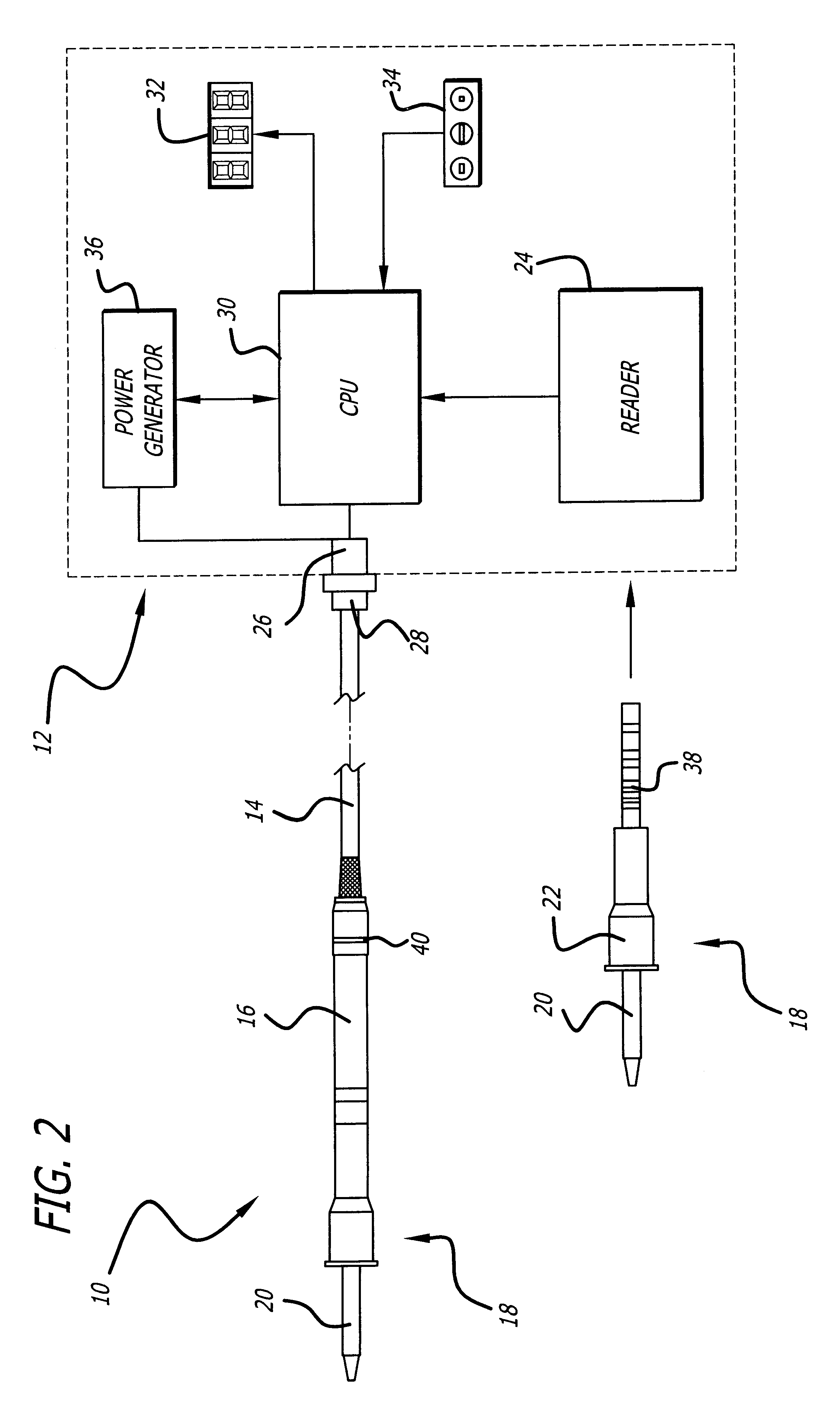
FIG. 2 is a block diagram indicating the flow of information within the soldering system of FIG. 1;

FIG. 3 depicts the cartridge, handle assembly and connector of the power cable;

FIG. 4 is a side and partial cross-sectional view of the connector;

FIG. 5 is a frontal view of the reader on the power supply;

FIG. 6 is a side view of the reader of the power supply;

FIG. 7 is a cross-sectional view of the reader depicting the sensors and switch inside of the power supply;

FIG. 8 shows a cartridge just before it is inserted into a cross-sectional view of the reader; and

FIG. 9 shows a cartridge inserted into a cross-sectional view of the reader.

FIG. 1 depicts a perspective view of an automated soldering system 10 according to the present invention. The automated...


PUM

PropertyMeasurementUnit
Temperatureaaaaaaaaaa
Poweraaaaaaaaaa
Currentaaaaaaaaaa

Abstract

An automated soldering system with an intelligent power supply that can automatically configure the power output to interchangeable soldering cartridges, where the soldering cartridges include readable information to allow the power supply to properly power the cartridge to achieve a desired, entered operating temperature. The system includes a cartridge with an identifier that contains information particular to that cartridge, a reader able to read that information, and an indicator positioned on a connector into which the cartridge is inserted.

Description

1. Field of the Invention:The present invention relates to an automated soldering system with an intelligent power supply that can automatically configure the power output to interchangeable soldering cartridges, where the soldering cartridges include readable information to allow the power supply to properly power the cartridge to achieve a desired, entered operating temperature. In particular, the present invention encompasses the use of an identifier on the cartridges and a reader coupled to the power supply for immediate recognition of the type of soldering cartridge to be used. In addition, to inform the user that the station is operational, a LED indicator preferably located proximate to the interchangeable cartridge and activated by the automated soldering system displays various light signals for the user.2. General Background and State of the Art:Soldering stations have been in use for many years. The typical soldering station includes two components: a soldering iron compo...

Claims


Application Information

Patent Timeline
IPC IPC(8): B23K3/03B23K3/02
CPCB23K3/033B23K3/03
Inventor YOKOYAMA, TETSUOMIYAZAKI, MITSUHIKOHAGIHARA, YOSHIHIRO
Owner HAKKO CO LTD
Why Eureka
Try Eureka