Guide plate, surface light source device of side light type and liquid crystal display
a technology of surface light source and liquid crystal display, which is applied in the direction of lighting and heating equipment, instruments, machines/engines, etc., can solve the problems reducing illumination quality, so as to avoid the effect of reducing illumination quality and avoiding the effect of reducing display quality
- Summary
- Abstract
- Description
- Claims
- Application Information
AI Technical Summary
Benefits of technology
Problems solved by technology
Method used
Image

Examples
first embodiment
(1) First Embodiment
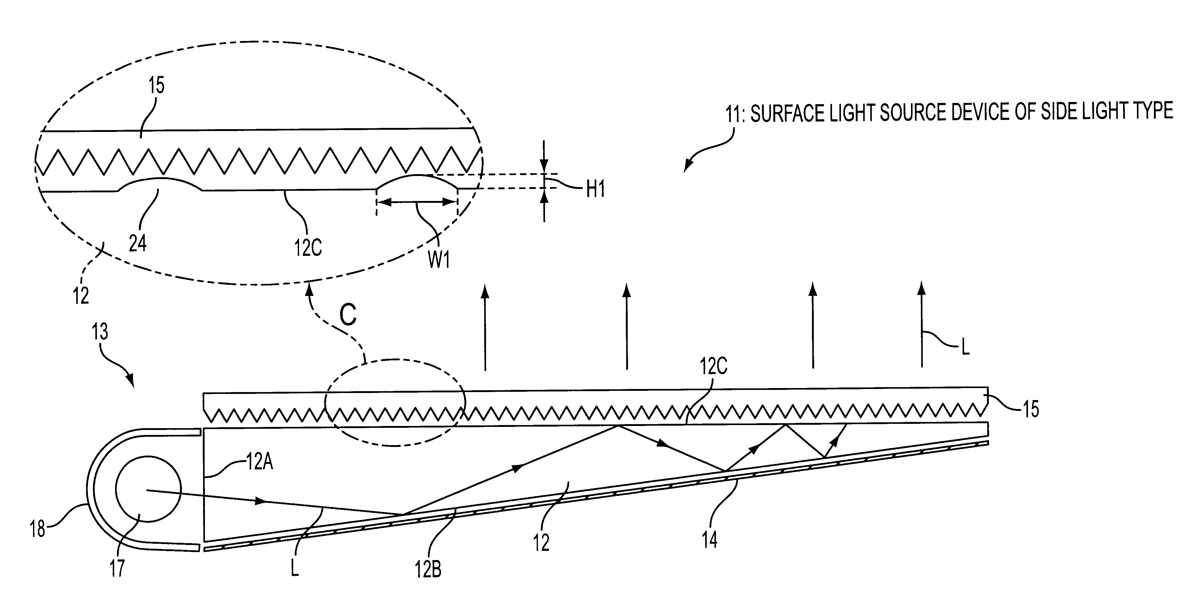
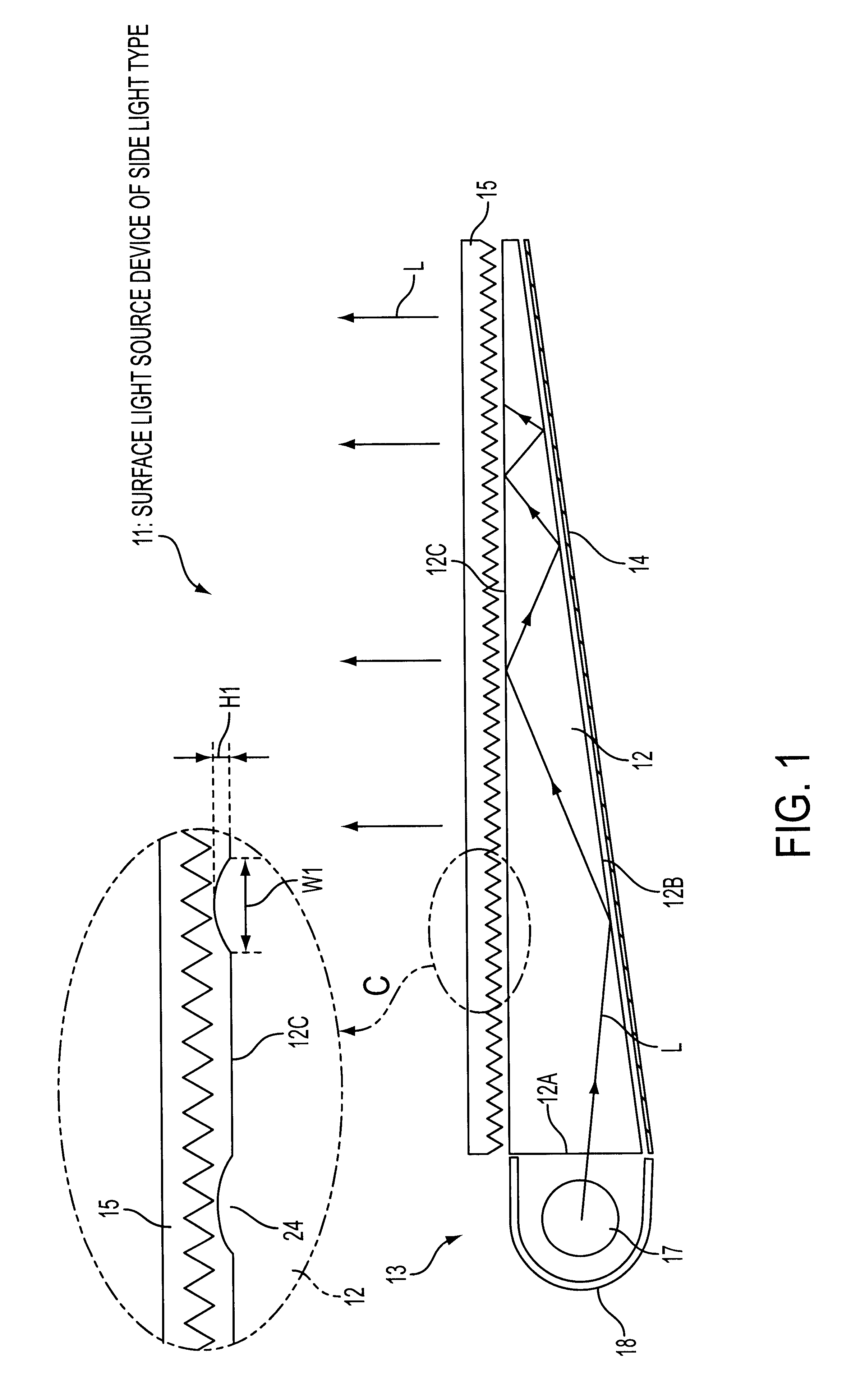
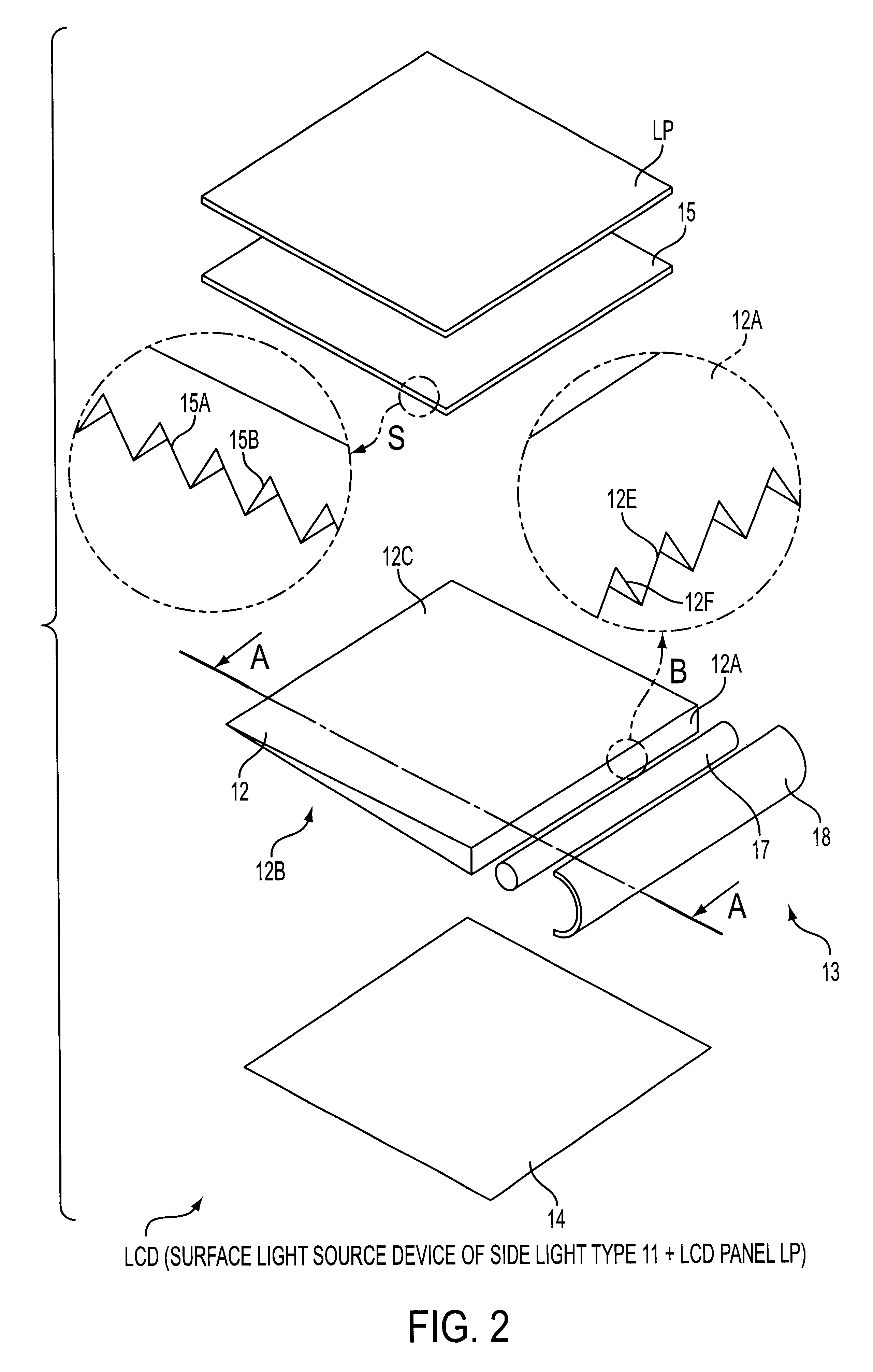
Referring to FIG. 2, a liquid crystal display employs a surface light source device of side light type 11 for backlighting of a liquid crystal display panel LP. The surface light source device 11 comprises a guide plate 12, a rod-like fluorescent lamp 17, a reflector 18, a reflection sheet 14 and a prism sheet 15 as a light control member. The reflection sheet 14, the guide plate 12 and the prism sheet 15 are laminatedly arranged and fixed by means of a frame member (not shown).
The guide plate 12 is made of, for example, a transparent material such as acrylic resin. The guide plate 12 has an emission face and a back face as major faces. The back face 12B provides a prism face (light control face), as depicted in a partially enlarged illustration with arrow B.
The reflection sheet 14 is a regular-reflection member such as provided with evaporation-deposited silver or an irregular-reflection member such as made of white PET (polyethylene terephthalate). The reflecti...
second embodiment
(2) Second Embodiment
This embodiment is different from the first embodiment in that a scattering guide plate 32 as shown in FIG. 4 is employed instead of the guide plate 12. The other matters include nothing different in particular. Accordingly, description of the second embodiment is focused on features of the scattering guide plate 32.
The scattering guide 32 is a guide plate which has scattering power inside and is composed of, for example, matrix made of polymethylmethacrylate (PMMA) and light-permeable particles dispersed uniformly in the matrix. The light-permeable particles have refractive index different, from that of the matrix, thereby being provided with inside scattering power.
The scattering guide plate 32 also has a wedge-shaped cross section. Such wedge-shaped cross section and inside scattering power help emission from an emission face 32C. A back face provides a prism face formed in the same manner as the case of the guide plate 12.
In the same manner as in the case of...
third embodiment
(4) Third Embodiment
Referring to FIG. 6, a LCD employs a surface light source device of side light type 41 for backlighting a LCD panel LP. The surface light source device 41 has the same structure as that of the surface light source device 11 (first embodiment) except that a guide plate 42 is employed instead of the guide plate 12.
Referring to FIG. 7 as well as FIG. 6, a surface light source device 41 comprises a rod-shaped fluorescent lamp 47, a reflector 48, a reflection sheet 44 and a prism sheet 45 as a light control member. The reflection sheet 14, the guide plate 42 and the prism sheet 45 are laminatedly arranged and fixed by means of a frame member (not shown).
The guide plate 42 is made of, for example, a transparent material such as acrylic resin. The guide plate 42 has an emission face 42C and a back face 42B as major faces. The reflection sheet 44 is a regular-reflection member such as provided with evaporation-deposited silver or an irregular-reflection member such as ma...
PUM
 Abstract
Description
Claims
Application Information
 - R&D Engineer
- R&D Manager
- IP Professional
- Industry Leading Data Capabilities
- Powerful AI technology
- Patent DNA Extraction
Browse by: Latest US Patents, China's latest patents, Technical Efficacy Thesaurus, Application Domain, Technology Topic.
© 2024 PatSnap. All rights reserved.Legal|Privacy policy|Modern Slavery Act Transparency Statement|Sitemap