
High-brightness color liquid crystal display panel employing light recycling therein

a liquid crystal display and color technology, applied in the field of high-brightness color liquid crystal display panels, can solve the problems of light transmission, inability to produce high-brightness images from prior art color lcd panels used in direct or projection display systems, and achieve the effects of reducing manufacturing costs, increasing viewing angles, and facilitating color production

Inactive Publication Date: 2003-06-03
REVEO
View PDF13 Cites 151 Cited by
  • Summary
  • Abstract
  • Description
  • Claims
  • Application Information

AI Technical Summary

Benefits of technology

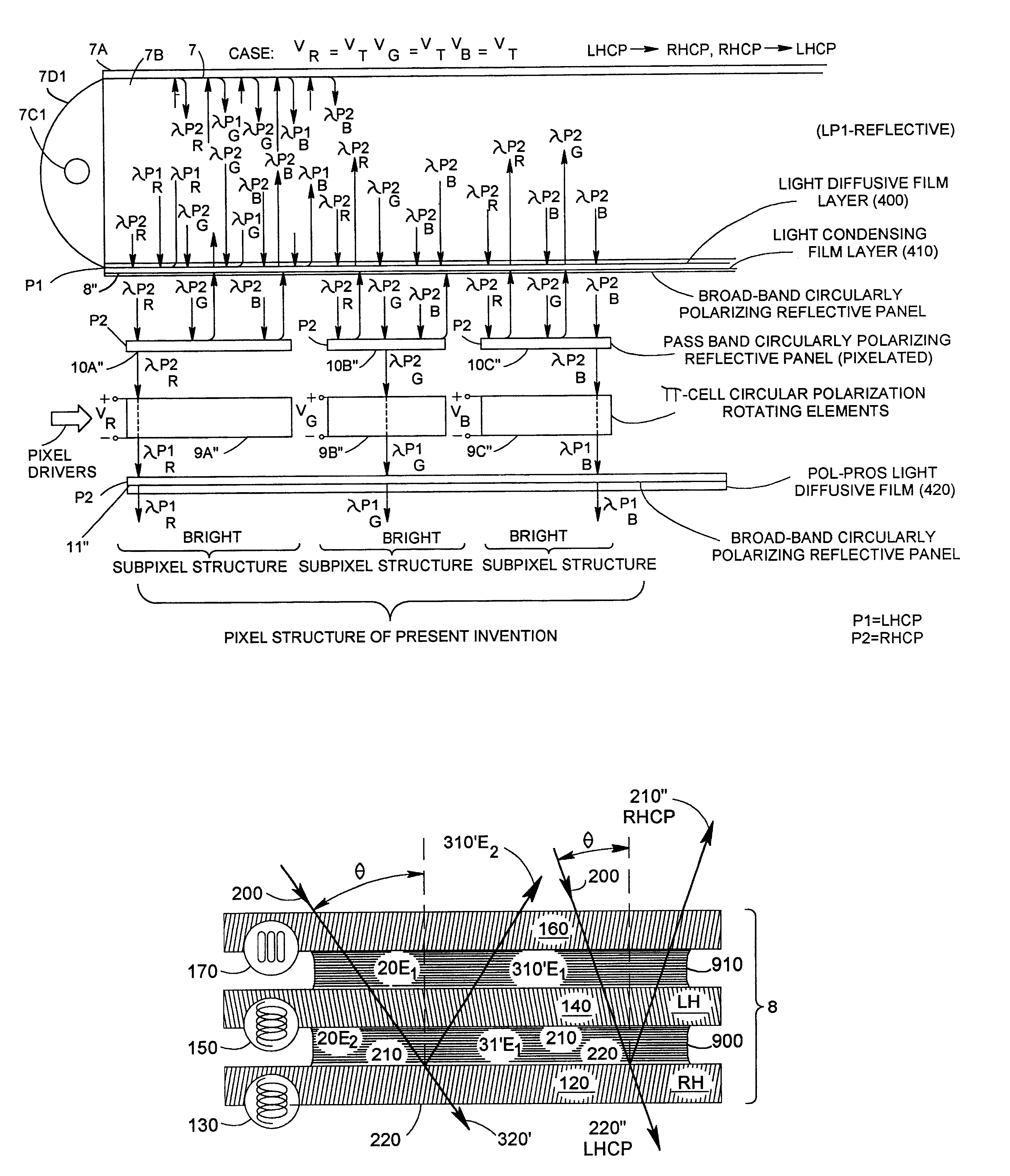
Accordingly, a primary object of the present invention is to provide an improved color LCD panel capable of producing high brightness color images, while avoiding the shortcomings and drawbacks of prior art techniques. Another object of the present invention is to provide such a color LCD panel, in which the spatial-intensity modulation and spectral (i.e. color) filtering functions associated with each and every subpixel structure of the LCD panel are carried out using systemic light recycling principles which virtually eliminate any and all absorption or dissipation of the spectral energy produced from the backlighting structure during color image production.
FIG. 36 is a schematic representation of an exploded, partially cut away cross-sectional view of an alternative embodiment of the LCD panel construction shown in FIGS. 32A1 and 32A2, wherein the spatial-intensity modulating elements of the LCD panel are realized using linear-type polarization rotating elements, the pixel driver signals provided thereto are selected to produce "dark" output levels the red and blue subpixels of the exemplary pixel structure and a "bright" output level at the green subpixel level, and broad-band absorptive linear polarizer is used in conjunction with each broad-band polarizing reflective panel in the LCD panel in order to provide improved image contrast in images displayed therefrom;

Problems solved by technology

However, using prior art design techniques, it has been impossible to achieve this design goal due to significant losses in light transmission caused by the following factors, namely: absorption of light energy due to absorption-type polarizers used in the LCD panels;--absorption of light reflected off thin-film transistors (TFTs) and wiring of the pixelated spatial intensity modulation arrays used in the LCD panels; absorption of light by pigments used in the spectral filters of the LCD panels; absorption of light energy by the black-matrix used to spatially separate the subpixel filters in the LCD panel in order to enhance image contrast; and Fresnel losses due to the mismatching of refractive indices between layers within the LCD panels.
Thus, it is impossible to produce high brightness images from prior art color LCD panels used in either direct or projection display systems without using ultra-high intensity backlighting sources which require high power supplies, and produce great amounts of heat necessitating cooling measures and the like.
As a result of such light energy losses, it has been virtually impossible to improve the light transmission efficiency of prior art LCD panels beyond about 5%.
While U.S. Pat. No. 5,822,029 discloses an LCD panel construction having the above-described improvements, this prior art LCD panel system nevertheless suffers from a number of significant shortcomings and drawbacks.
For example, the manufacturing of CLC layers having three color regions or sections is quite difficult because of the limited dynamic range in color tuning afforded by the CLC manufacturing techniques disclosed in U.S. Pat. No. 5,822,029 and other prior art references.
Adding the reflective-type black matrix pattern to the CLC spectral filter structure increases the complexity of the display system and adds to the overall cost of the display which must be minimized for low-cost consumer product applications.
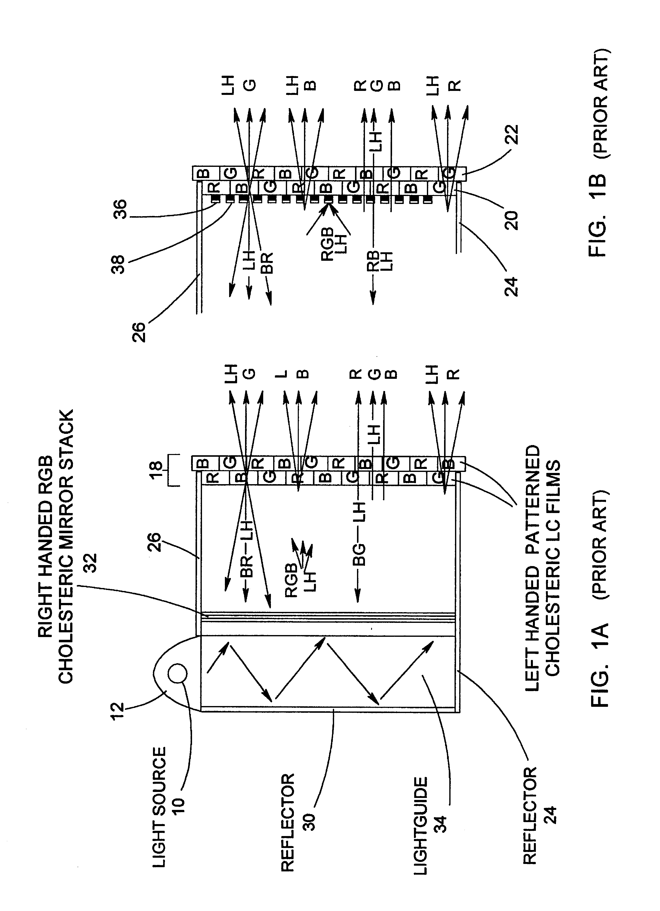
While recommending the use of light collimation techniques to ensure that the incident upon the spectral filter falls within the angular acceptance bandwidth of its CLC material, U.S. Pat. No. 5,822,029 fails to disclose, teach or suggest practical ways of achieving this requirement of CLC material, nor even recognizes in the slightest way the fact that non-collimated light falling on the broad-band CLC reflective polarizer (32) results in significant polarization distortion, as illustrated in FIGS.
While U.S. Pat. No. 5,822,029 discloses the use of CLC-based spectral filters for improved light recycling within a LCD panel, the methods taught therein necessarily result in CLC films having narrow bandwidths which limited their usefulness in creating practical color (i.e. spectral) filter structures for use in LCD panels.
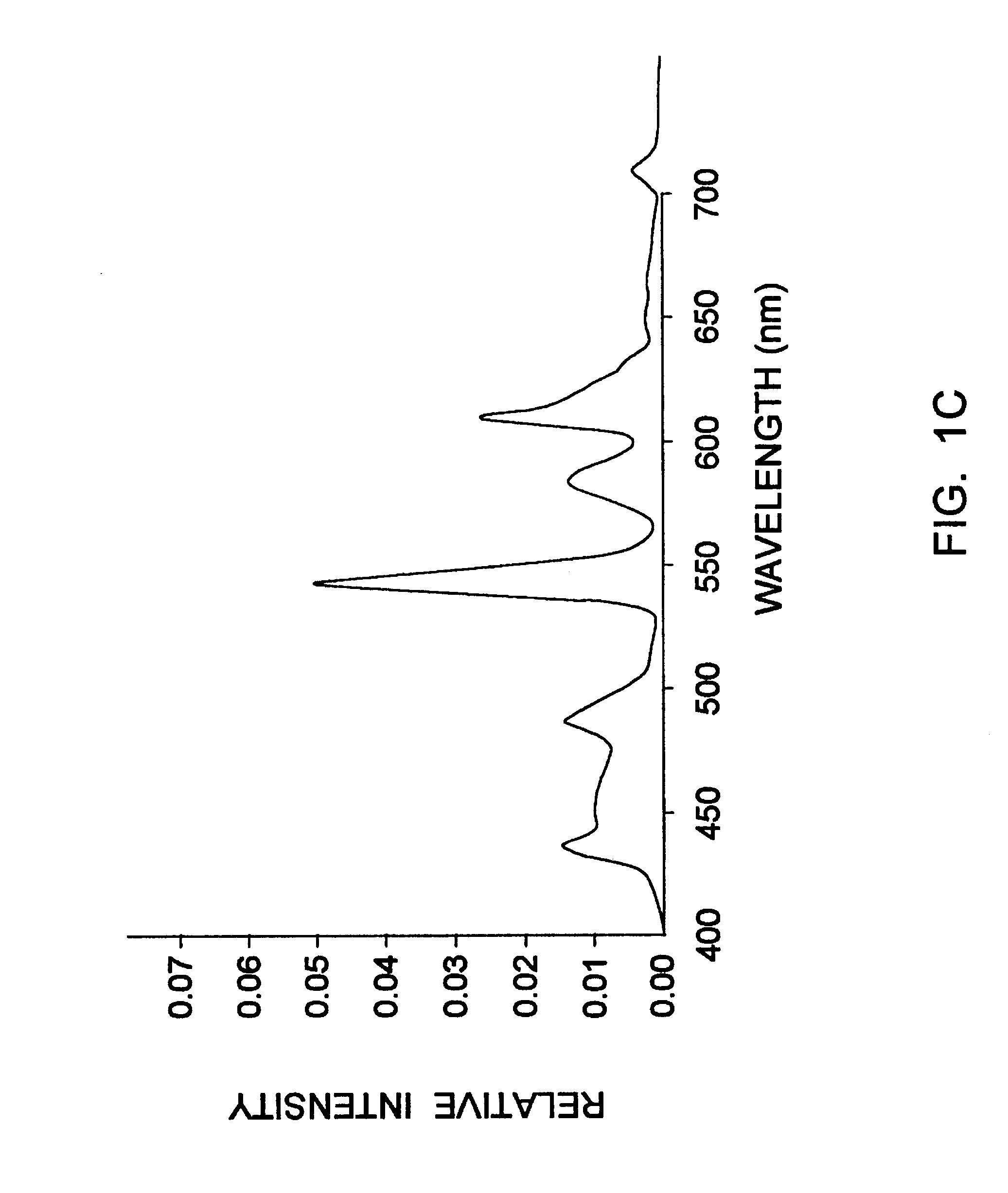
While U.S. Pat. No. 5,822,029 discloses a technique of increasing the bandwidth of the cholesteric liquid crystal material by providing a plurality of different pitches in each portion of the material (e.g. use a thermochromic material and vary its temperature while applying ultraviolet light to fix the material), this method is difficult to use in practice and does not produce good results because the bandwidth of the reflective materials is limited to about 80 nm.
The CLC-based spectral filters disclosed in U.S. Pat. No. 5,822,029 do not had a sufficient broad enough spectral bandwidth to reflect all the light needed to made a good quality color reflective filter.
In summary, while it is well known to use CLC-based spectral filters and CLC reflective polarizers within color LCD panel assemblies to improve the brightness of images displayed therefrom, prior art CLC-based LCD panels suffer from several shortcomings and drawbacks relating to: (1) color changes due to viewing angle; (2) controlling the bandwidth of the spectral components to be reflected within the panel for recycling; (3) difficulty in tuning the color-band of spectral components to be transmitted to the viewer for display; (4) difficulty in achieving high contrast between the spectral components in different color bands; (5) difficulty in making CLC-based spectral filter layers which result i n spectral filters having high color purity and a broad color gamut; and (6) realizing a reflective-type black matrix which is inexpensive and does not increase the complexity of the system.

Method used


Image

  • High-brightness color liquid crystal display panel employing light recycling therein
  • High-brightness color liquid crystal display panel employing light recycling therein
  • High-brightness color liquid crystal display panel employing light recycling therein

Examples


Embodiment Construction

Referring now to the figures in the accompanying Drawings, the illustrative embodiments of the present invention will now be described in detail, wherein like structures and elements shown within the figures are indicated with like reference numerals.

Systemic Light Recycling within the LCD Panel of the Present Invention

The light transmission efficiency of prior art LCD panels has been severely degraded as a result of the following factors: absorption of light energy due to absorption-type polarizers used in the LCD panels; absorption of light reflected off thin-film transistors (TFTs) and wiring of the pixelated spatial intensity modulation arrays used in the LCD panels; absorption of light by pigments used in the spectral filters of the LCD panels; absorption of light energy by the black-matrix used to spatially separate the subpixel filters in the LCD panel in order to enhance image contrast; and Fresnel losses due to the mismatching of refractive indices between layers within the...


PUM

PropertyMeasurementUnit
angleaaaaaaaaaa
angleaaaaaaaaaa
angleaaaaaaaaaa

Abstract

Reflective color filters using layers of cholesteric liquid crystals with two different center wavelengths and bandwidths per layer are stacked in two layers to provide colored light for displays. With a two layer stack circularly polarized light of one handedness can be provided. With a two layer stack circulary unpolarized colored light can be provided. With a broadband polarizing filter overlapping other filters in the stack a black matrix can be provided by reflecting all colors and transmitting no light in the overlapping areas. When broadband reflective cholesteric liquid crystals are used two primary colors can be reflected in the same pixel of a display making reflective layers with two reflective portions per layer possible. Color displays having three linear sub-pixels with three primary colors or with four sub-pixels of white, blue, green, and red in a pixel with two colors in a top row and two colors on a bottom row can are made with two colors per layer in two layer stacks. The pixels in the display are arranged such that multiple adjacent sub-pixels in a layer, or row in a layer, with the same color makes the color filters easier to manufacture. Displays using these reflective color filters may have a reflective polarizer for viewing the display at wide angles without color distortion.

Description

BACKGROUND OF INVENTION1. Technical FieldThe present invention relates to a high-brightness color liquid crystal display (LCD) panel with improved image contrast employing non-absorptive spectral filtering, light recycling among neighboring subpixels and ambient glare reduction, and also to methods and apparatus for manufacturing the same.2. Brief Description of the Prior ArtWithout question, there is a great need for flat display panels capable of displaying video imagery in both direct and projection modes of viewing. Examples of equipment requiring such display structures for direct viewing include notebook computers, laptop computers, a and palmtop computers, and equipment requiring such display structures for projection viewing include LCD projection panels and LCD image projectors.In general, prior art color LCD display panels have essentially the same basic construction in that each comprises the following basic components, namely: a backlighting structure for producing a pla...

Claims


Application Information

Patent Timeline
Patent Type & Authority Patents(United States)
IPC IPC(8): C09K19/54E06B9/24F24J2/40G01D11/28G02F1/1335G02B27/00G02B5/30G02F1/13G02F1/1347G02F1/139G02F1/1334G02F1/137F21V8/00G02B6/00G02F1/13357
CPCB82Y15/00E06B9/24F24J2/407G01D11/28G02B5/3016G02B6/0056G02B27/0093G02F1/133514G02F1/133536G02F1/13362G02F1/133621G02F1/13471G02F1/1393C09K19/544Y02E10/40E06B2009/2464G02B6/0051G02B6/0053G02B6/0055G02F1/1334G02F1/13718G02F2001/133543G02F2001/133623F24S50/80G02F1/133543G02F1/133623
Inventor JIANG, YINGQIULI, LEHOCHBAUM, AHARONVARTAK, SAMEERGALABOVA, HRISTINAWILEY, RICHARDFARIS, SADEG M.
Owner REVEO
Learn More