
Actuation device for a friction clutch

a technology of friction clutch and actuation device, which is applied in the direction of fluid actuation clutch, non-mechanical actuation clutch, clutch, etc., can solve the problems of instability and vibration, defects in the dynamic behavior of the actuation device, and the exposure of the pressure medium force ring cylinder in the housing cover to comparatively high thermal loading

Inactive Publication Date: 2003-06-10
ZF FRIEDRICHSHAFEN AG
View PDF7 Cites 10 Cited by
  • Summary
  • Abstract
  • Description
  • Claims
  • Application Information

AI Technical Summary

Benefits of technology

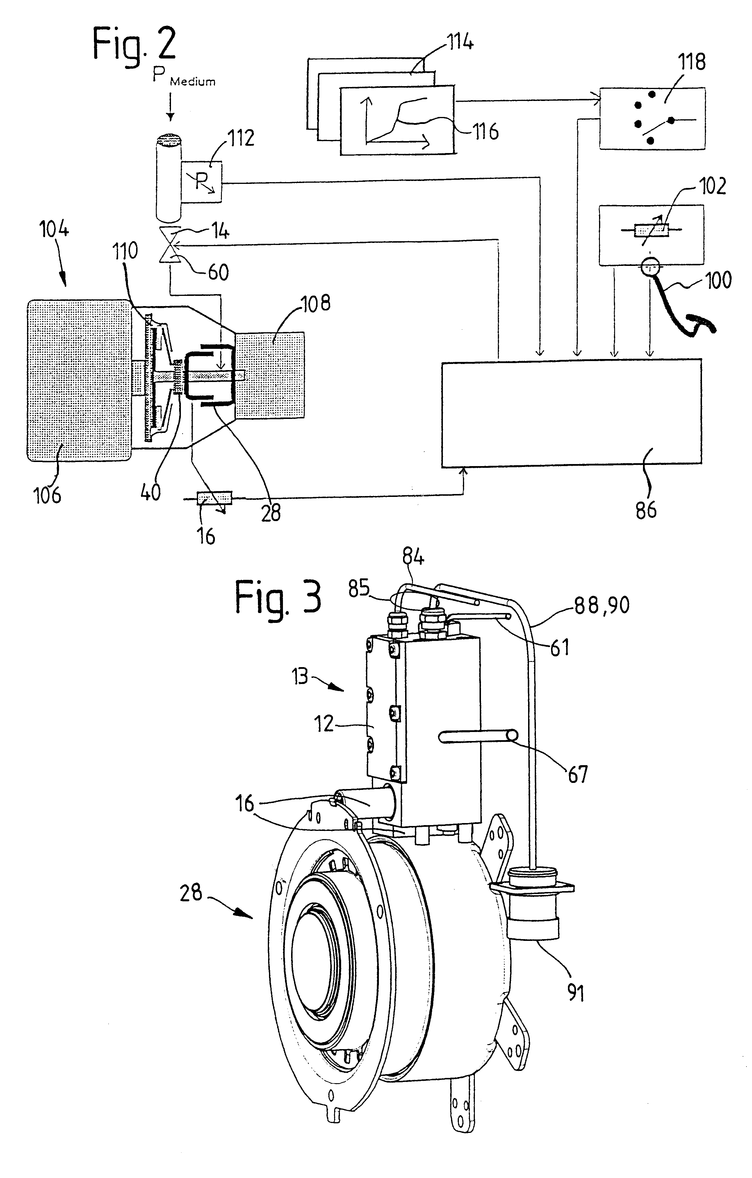
For example, a startup and / or maneuvering characteristic line with a spread slip point associated with a startup and / or maneuvering situation can be provided in order to facilitate startup and / or maneuvering. Another possibility would be to provide an upshift and / or downshift characteristic line without a spread slip point associated with an upshift and / or downshift situation in order to minimize slip states of the friction clutch with respect to time and accordingly to counteract clutch wear.
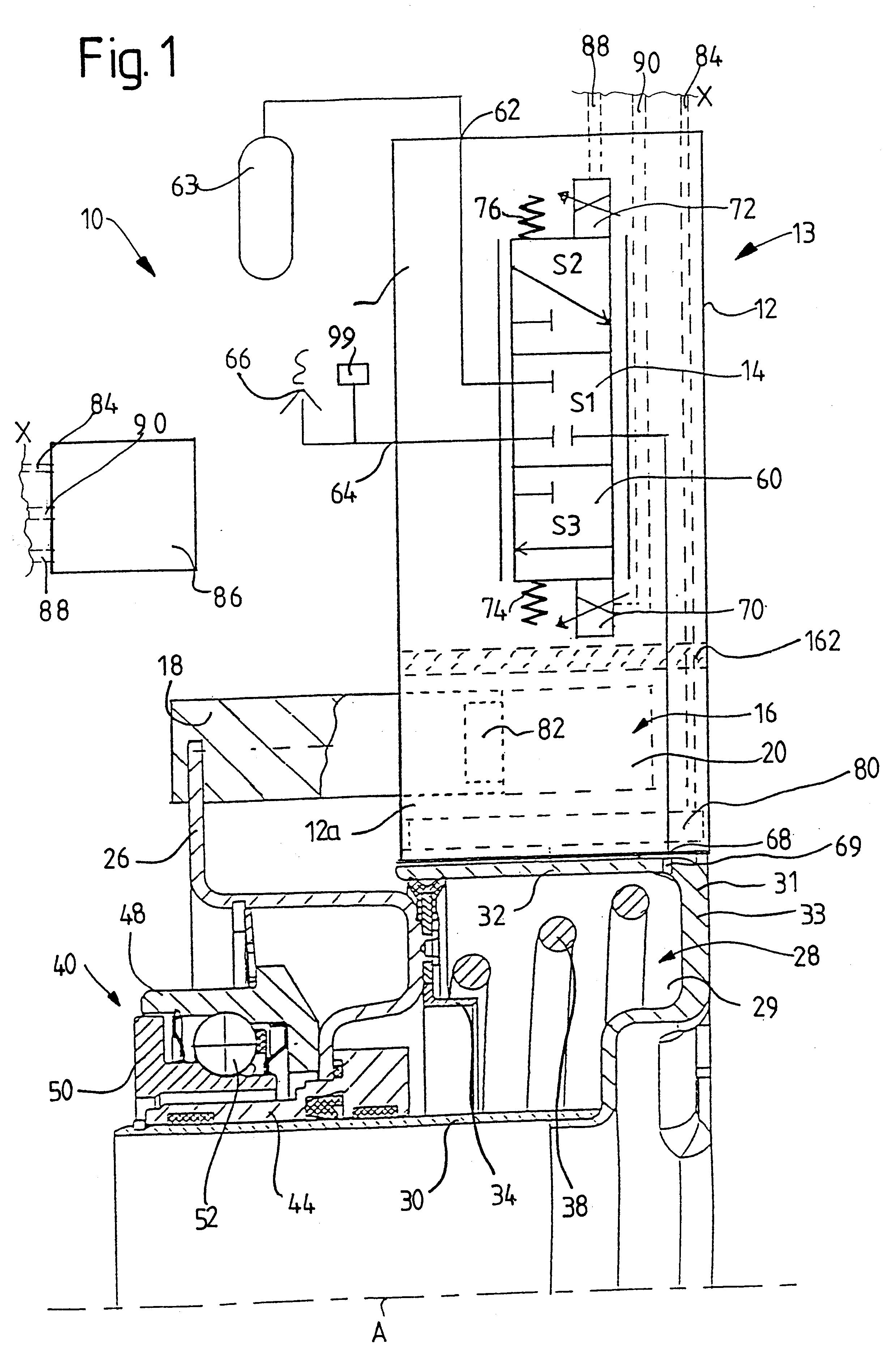
In order to substantially reduce the thermal loading for the heat-sensitive region of the constructional unit (for example, the control / regulating valve arrangement) or to eliminate any thermal loading, the heat-sensitive region of the constructional unit (which can include the control / regulating valve arrangement) can project out of the latter through a housing cover opening. In this connection, it is particularly advisable when the wall of the housing cover has a recessed wall part in which the housing cover opening is provided, the housing cover opening being disposed at an inner end portion of a surrounding wall portion of the recessed wall part.
In this way, it can be achieved that at least the heat-sensitive area of the constructional unit is shielded relatively well against the thermal loading inside the housing cover and heat occurring in the hear-sensitive area of the constructional unit or heat which is transferred to the constructional unit through heat transfer can be discharged to the outside comparatively effectively. In this case, the thermal separating layer of the constructional unit can even be dispensed with under certain circumstances. According to a third aspect, the invention provides a corresponding actuation device. Preferably, however, a thermal separating layer is provided, which can be particularly effective when it is arranged roughly at the height of the wall portion defining the housing cover opening.
According to this inventive suggestion, heat-sensitive components, especially the control / regulating valve arrangement, can be arranged outside the housing cover in order to reduce thermal loading thereon. Nevertheless, as with the actuation devices according to the first, second and third aspects, it is possible to integrate components serving to control the pressure medium force cylinder arrangement, especially the control / regulating valve arrangement and the measuring arrangement enabling exact positioning, in one or more constructional units resulting in a simple, economical and manageable construction and enabling a simple, economical assembly. When a constructional unit and a separate valve constructional unit (in which other components can also be integrated) are provided, the expenditure on assembly is only slightly higher compared with integration of the control / regulating valve arrangement in the constructional unit arranged at the pressure medium force ring cylinder, this slight increase being more than offset by the advantages achieved with respect to the reduced or even eliminated thermal loading of the control / regulating valve arrangement. Beyond this, the valve constructional unit is substantially more accessible because of its arrangement outside the housing cover, so that maintenance is substantially facilitated. As a rule, the measuring arrangement can be advantageously integrated in the constructional unit arranged at the pressure medium force ring cylinder.
Compared with the arrangement known from EP 0 371 975 B1, in which the control / regulating valve arrangement is formed by four switching valves, two of which are associated with an engagement actuation while the other two are associated with a release actuation, the quantity of structural component parts can be appreciably reduced according to the inventive suggestion with a consequent reduction in cost and simplification of the arrangement. The simplification of the arrangement results in advantages with respect to operating reliability.
A particularly preferred embodiment form is distinguished by the fact that the valve is a proportional solenoid valve. A large signal behavior which is substantially improved compared with the use of one or more switching valves is therefore achieved because a proportional valve can be opened very far, resulting in a large flow cross section for the pressure medium, particularly compressed air. With respect to small signal behavior, values are achieved which are as good as when one or more switching valve are provided.

Problems solved by technology

However, this is problematic in that the pressure medium force ring cylinder is exposed in the housing cover to comparatively high thermal loading which may not necessarily be withstood by the sensitive components of the actuation device.
The inventive idea is based on the thought that any intermediate components or transmission members between the pressure medium force cylinder arrangement and release bearing are disadvantageous with respect to idle times, phase displacements, hysteresis effects and so on, and can lead to defects in the dynamic behavior of the actuation device and, at worst, to instability and vibrations.

Method used


Image

  • Actuation device for a friction clutch
  • Actuation device for a friction clutch
  • Actuation device for a friction clutch

Examples


embodiment form

A possible embodiment form of the above-mentioned standard interface of the release cylinder 28 is shown in FIG. 5. Each of the three fastening pins 150 welded to the release cylinder 18 has an internal thread, so that a constructional unit (for example, constructional unit 13, 13', 13" or 13'") attached to the pin can be fixed by screws or the like. In addition to the fastening pins 150, an air inlet and outlet nipple 152 is provided which engages in a nipple receptacle 154 of the constructional unit which is mounted by means of the standard interface, wherein a sealing arrangement 156 acts between the nipple 152 and the nipple receptacle 154 as shown in FIG. 6. In this way, a pressure medium flow connection, especially a compressed air flow connection, is produced between a cylinder space of the actuation cylinder 28 and the control / regulating valve arrangement of the constructional unit mounted at the release cylinder 28 or a valve constructional unit which is separate from the c...


PUM


Abstract

In an actuation device for a friction clutch which is arranged in the drivetrain of a motor vehicle between a drive unit and a transmission, comprising a pressure medium force cylinder arrangement by means of which the friction clutch can be actuated via a release member, a measuring arrangement which detects an actual release, a control / regulating valve arrangement which is connected with a pressure medium source, with a pressure compensation opening or a pressure compensation reservoir and with the pressure medium force cylinder arrangement and which is controllable electrically, by means of which valve arrangement the pressure medium force cylinder arrangement can be actuated depending on the actual release and on a reference release which can be predetermined, the control / regulating valve arrangement can be actuated via control / regulating electronics depending on the actual release, on an electrically presettable command variable and on a characteristic line converting the command variable into the reference release, wherein several different characteristic lines are provided which can be selectively activated depending on a desired driving behavior and / or depending on driving states and / or operating states of the vehicle for actuating the valve arrangement.

Description

1. Field of the InventionThe present invention is directed to an actuation device for a friction clutch which is arranged in the drivetrain of a motor vehicle between a drive unit and a transmission, comprising a pressure medium force cylinder arrangement by means of which the friction clutch can be actuated via a release member, a measuring arrangement which detects an actual disengagement or release, a control / regulating valve arrangement which is connected with a pressure medium source, with a pressure compensation opening or a pressure compensation reservoir and with the pressure medium force cylinder arrangement and which is controllable electrically, by means of which control / regulating valve arrangement the pressure medium force cylinder arrangement can be actuated depending on the actual release and on a reference release which can be predetermined.2. Description of the Related ArtAn actuation device of the type mentioned above with an electrically controllable control / regul...

Claims


Application Information

Patent Timeline
Patent Type & Authority Patents(United States)
IPC IPC(8): F16D25/08F16D48/00F16D48/02F16D48/06
CPCF16D25/082F16D48/02F16D48/06F16D25/14B60W2710/022F16D2300/18F16D48/066F16D2500/1045F16D2500/3024F16D2500/3026F16D2500/31413F16D2500/31493F16D2500/702F16D2500/7041
Inventor DREXL, HANS-JURGENOTTO, THOMASFLIEGE, HANSSCHMITT, JURGEN
Owner ZF FRIEDRICHSHAFEN AG
Learn More