System for controlling an automatic transmission throttle valve

a technology of automatic transmission and throttle valve, which is applied in the direction of machines/engines, mechanical equipment, shafts and bearings, etc., can solve the problems that the linkage on older carburetors was never designed to provide the proper signal, and achieve the effect of firmness and aggressive respons

Inactive Publication Date: 2003-06-10
PAC INTERACTIVE TECH
View PDF11 Cites 7 Cited by
  • Summary
  • Abstract
  • Description
  • Claims
  • Application Information

AI Technical Summary

Benefits of technology

The present invention is directed to a system and method for controlling the throttle valve of automatic transmissions, and more particularly to a system and method which permits selective adjustment, or "tuning", of the rate at which the throttle valve is activated to adjust shift timing, firmness, and feel. This allows the installation of a modern throttle valve controlled automatic transmission into a vehicle for which it was not designed. Specifically, the linkage on older carburetors was never designed to provide the proper signal to newer throttle valve transmissions. The present invention provides a means of insuring not only the correct cable pull distance, but also of adjusting the characteristics of transmission operation. The present invention offers an installer the ability to accomplish both a correct cable pull distance which is a requirement fixed by the travel of the throttle valve while concurrently offering many different dynamic arc or cable pull relationships to "tune" the transmission response to a desired shift timing, firmness, and feel. One way this is accomplished is by giving the installer the ability to maintain the TV cable's approach angle in a fixed plane in relationship to the carburetor linkage. Through the use of spacers, a slot, and a hole pattern, the fixed plane may be raised or lowered to maintain a constant approach angle to the carburetor linkage attachment point. In a preferred embodiment, the approach angle is parallel to the bottom of the carburetor or fuel injection system. Another way the present invention allows the installer to tune the response is a sliding attachment point along a pre-engineered slot. The slot is designed to maintain a correct fixed pull distance at all slot positions while offering the installer wide latitude for adjusting the cable pull dynamics, including the rate at which the cable is pulled. As the attachment point is moved to different locations along the slot, the angular relationship between the pulling arm and the cable is changed. By using different settings along the slot, the transmission shift timing, firmness, and response aggressiveness can be adjusted over a wide spectrum. This provides the installer with a method of developing the desired transmission response while simultaneously maintaining the correct fixed cable pull distance.

Problems solved by technology

Specifically, the linkage on older carburetors was never designed to provide the proper signal to newer throttle valve transmissions.

Method used


Image

  • System for controlling an automatic transmission throttle valve
  • System for controlling an automatic transmission throttle valve
  • System for controlling an automatic transmission throttle valve

Examples


Embodiment Construction

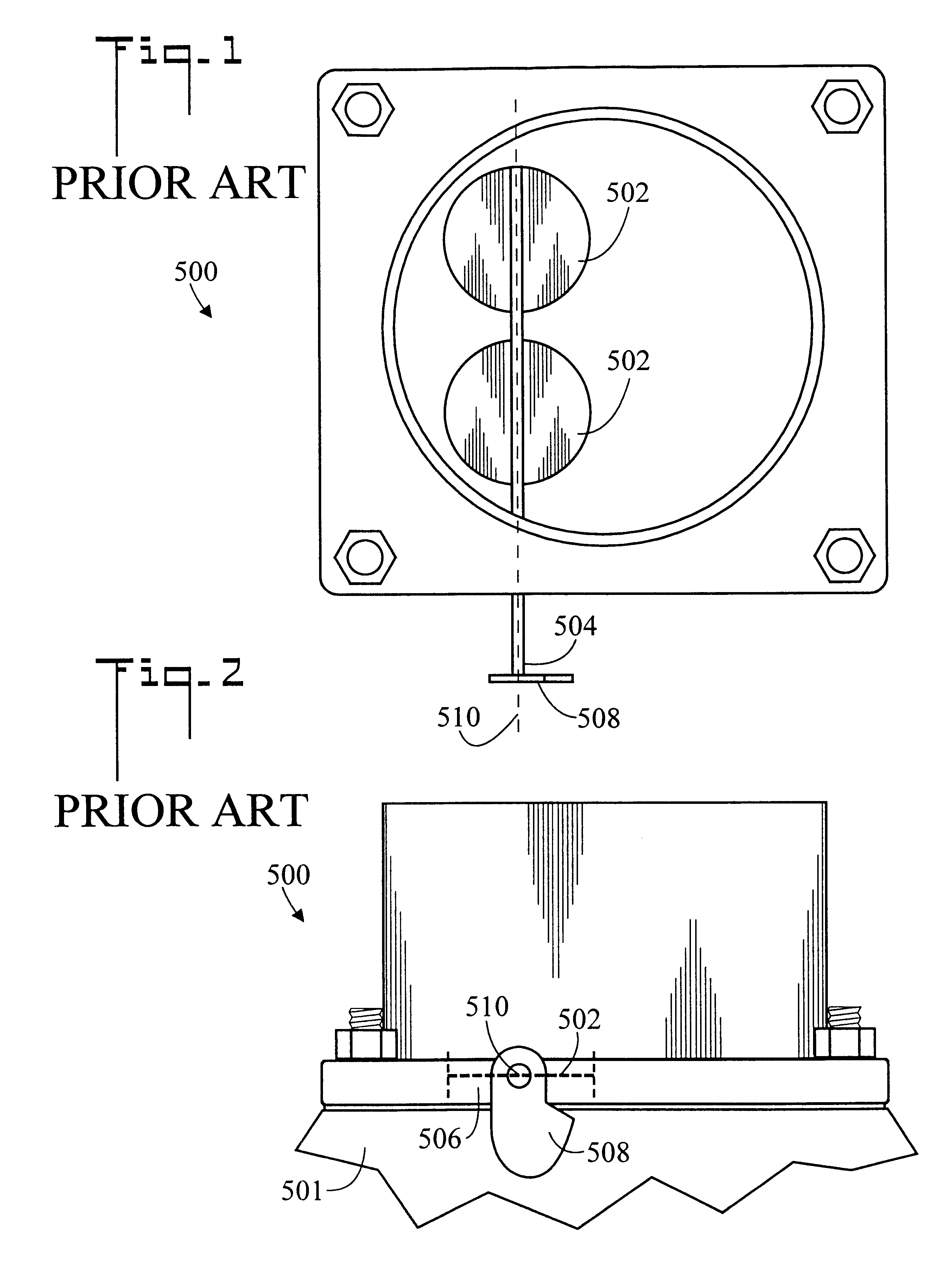
FIGS. 1 and 2 illustrate top plan and side elevation views, respectively, of a prior art fuel management device 500 in an idle state or position. The fuel management device 500 shown is a carburetor. The fuel management device 500 could also be a fuel injection system having a rotatable linkage. Fuel management device 500 is mounted on an intake manifold 501. Fuel management device 500 includes two butterfly valves 502 which control the intake of air. The butterfly valves 502 are connected to a rotatable throttle shaft 504. In the shown idle or low throttle position state, butterfly valves 502 are oriented so as to block air from entering air intake 506. A rotatable linkage member 508 or throttle lever or throttle linkage is attached to rotatable throttle shaft 504, so that when rotatable linkage member 508 is rotated by an accelerator pedal linkage (not shown), rotatable throttle shaft 504 will rotate about axis 510 and thereby rotate butterfly valves 502.

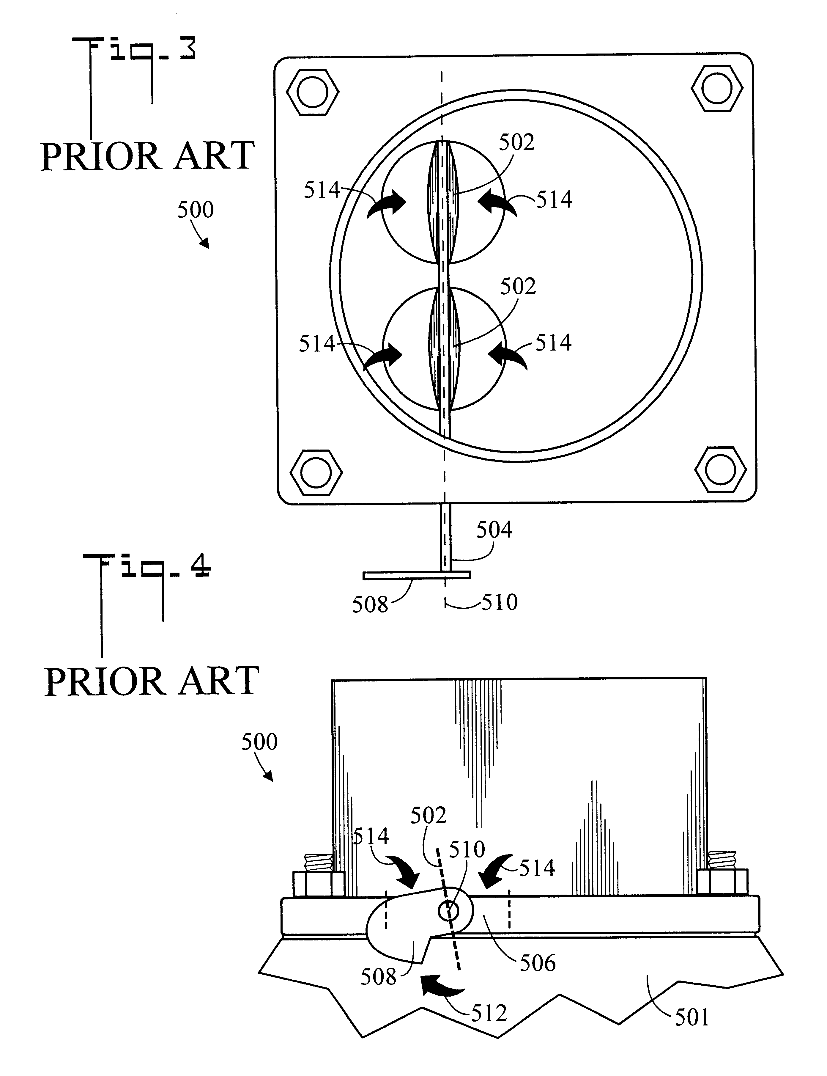
FIGS. 3 and 4 are top plan...


PUM


Abstract

A system (20) for controlling a transmission throttle valve in a vehicle having a fuel management device (500) having a rotatable linkage member (508) includes an adapter plate (22) which is mountable beneath the fuel management device (500), a bracket (26) which is connectable to the adapter plate (22), and a throttle valve cable (30) which is connectable to the bracket (26). Throttle valve cable (30) has a tubular housing (32) which is fixedly connectable to bracket (26) and a cable (34) which is slidably disposed within tubular housing (32), the cable (34) having a first end (36) and an opposite second end connectable to the transmission throttle valve. First end (36) is selectively connectable along a slot (40. Different first end (36) connection positions along slot (40) result in correspondingly different rates of cable pull and therefore different transmission responses.

Description

The present invention pertains generally to automobiles having automatic transmissions, and particularly to a system for selectively controlling the actuation rate of the automatic transmission throttle valve.The throttle valve, which is slidably movable in a bore, regulates the flow of transmission oil through the transmission's valve body. A linkage couples the position of the accelerator pedal to the throttle valve, and causes the throttle valve to move between an idle or low throttle position and a full or wide open throttle position. Throttle valve controlled transmissions utilize a cable running from the vehicle's fuel management system whether a fuel injector or carburetor to the transmission's valve body. The cable linkage between a modem fuel injector / carburetor system provides a signal method for proper transmission function. The cable connection is commonly known as the throttle valve (TV) cable. The TV cable connects the throttle mechanism to the transmission hydraulic c...

Claims


Application Information

Patent Timeline
Patent Type & Authority Patents(United States)
IPC IPC(8): F02D11/04F02D11/00F02D9/02
CPCF02D11/04F02D2009/0257Y10T74/2045Y10T477/693F02D2009/0279
Inventor HOLMES, STEPHEN G.
Owner PAC INTERACTIVE TECH
Why Eureka
Try Eureka