Electrical wiring system for the drive unit in vehicles

a technology for electric wiring and drive units, which is applied in the direction of insulated conductors, cables, conductors, etc., can solve the problems of increasing weight and volume, increasing the weight and volume of wire looms, and requiring a large number of manual processes to produce such a wiring loom

Inactive Publication Date: 2003-06-10
BAYERISCHE MOTOREN WERKE AG +1
View PDF24 Cites 25 Cited by
  • Summary
  • Abstract
  • Description
  • Claims
  • Application Information

AI Technical Summary

Benefits of technology

Such standardized interconnections can be produced in an automated process, since the interconnections themselves no longer contain circuits. This results in corresponding production advantages, and manual production effort can be minimized in the wiring that is the object of the invention.
Also, mounting the central distribution unit on the drive unit directly in accordance with the invention and integrating the electronic control modules within the central distribution unit can considerably reduce the extent of the wiring and save wire length. The electronic control modules that correspond in functional terms to the control devices that have been customary up to the present, may now, according to the invention, be integrated without an individual casing directly on the control platform. For this purpose, the control platform is configured preferably as a fixed or flexible circuit board or FPC (flexible printed circuit) plate. It may, however, also be configured as a fixed or flexible circuit component in other suitable techniques that are known to the skilled person, for example as a printed or etched circuit board or using MID (moulded interconnect device) technology. The control platform also preferably includes the contact points and interfaces to the interconnections.
A bus connection cable may also be used to connect the central distribution unit with the vehicle using multiplex technology. As a whole the number of first connecting wires can be minimized. As far as the electrical power supply is concerned, only a single supply wire which connects the central distribution unit with the vehicle battery is required. In contrast to the increasing thickness of the traditional wiring harness towards its base, the invention minimises the number of first connections between the vehicle and the distribution unit. These require less space and can easily be placed within the engine compartment.
Thanks to the modular concept of the invention, technical modifications of the wiring can also be carried out relatively easily by means of a corresponding modification of the distribution unit, whereas until now the complete structure of the wiring harness had to be modified.
The invention results in a wiring concept that is well suited for extensively automated production that can be optimised as far as the construction volume is concerned, that is flexible in terms of constructing variants and technical modifications and that is distinguished by a clearly organized wiring structure. The number of plug-in connections is reduced, and thus costs and assembly expenditure are also reduced. Thanks to the clearly organized spatial structure of the wiring that is object of the invention wiring mistakes during assembly can be reduced, i.e. another increase in quality can be achieved, and the replacement of individual interconnections can be achieved without problems. Also electromagnetic compatibility problems can be minimized, since interference-prone wires are placed far away from the corresponding sources of interference by means of a corresponding wiring configuration. Thanks to the carrier function of the central distribution unit for components with electrical and / or electronic functions, such as ignition high-stage levels, fuse switches or control devices, the number of interconnections required and the number of plug-in connections can be further optimised.

Problems solved by technology

The production of such a wiring loom requires a large number of manual processes.
Another problem is that, due to the drastically increasing number of functional units and functional contents of engines and transmissions, the wiring looms contain more and more wires and thus increase in weight and volume.
Thus, the technical designers face increasing difficulties when accommodating the wiring loom in the engine compartment.
The result is, on the one hand, that the E-box is of a considerable size, which in turn, triggers positioning problems, and on the other hand it is time-consuming to assemble due to the manual assembly of the numerous plug-in connections between the wiring loom and the E-box.

Method used


Image

  • Electrical wiring system for the drive unit in vehicles
  • Electrical wiring system for the drive unit in vehicles
  • Electrical wiring system for the drive unit in vehicles

Examples


Embodiment Construction

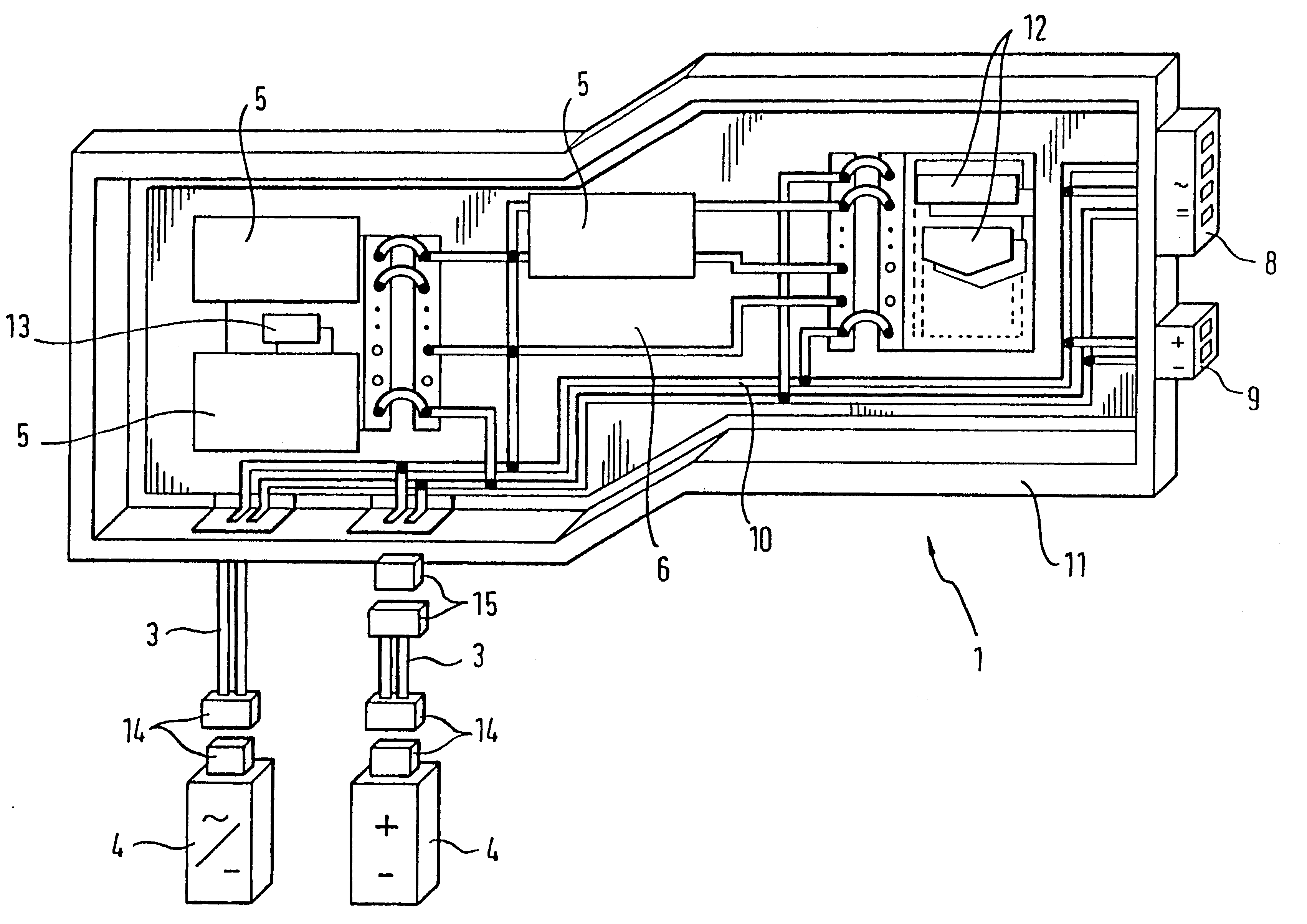
The invention is based on the technical problem of creating an electrical wiring system for the drive unit in a vehicle in which the issue of accommodating the wiring is improved, whilst at the same time simplifying the manufacture and installation of the wiring.

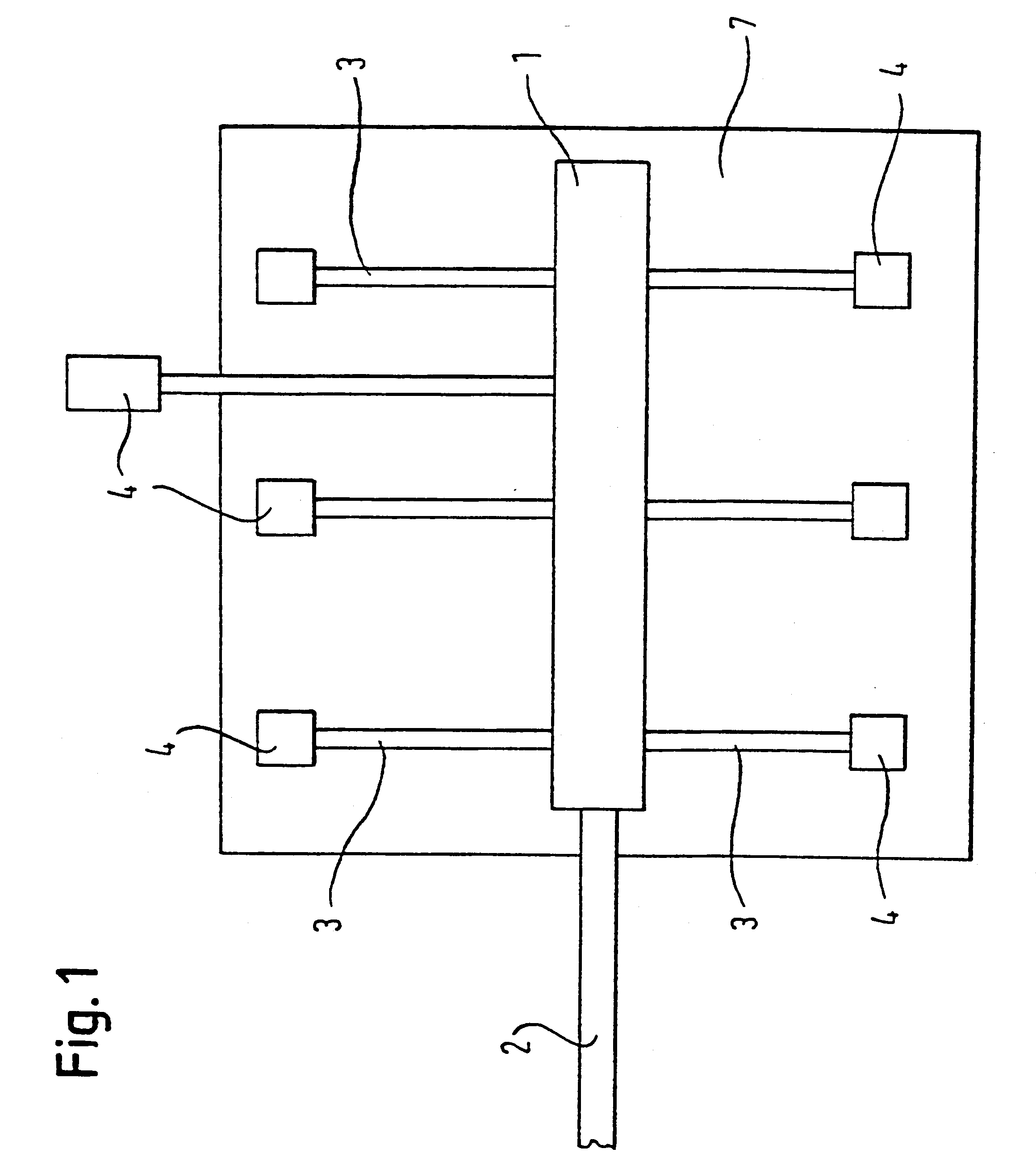
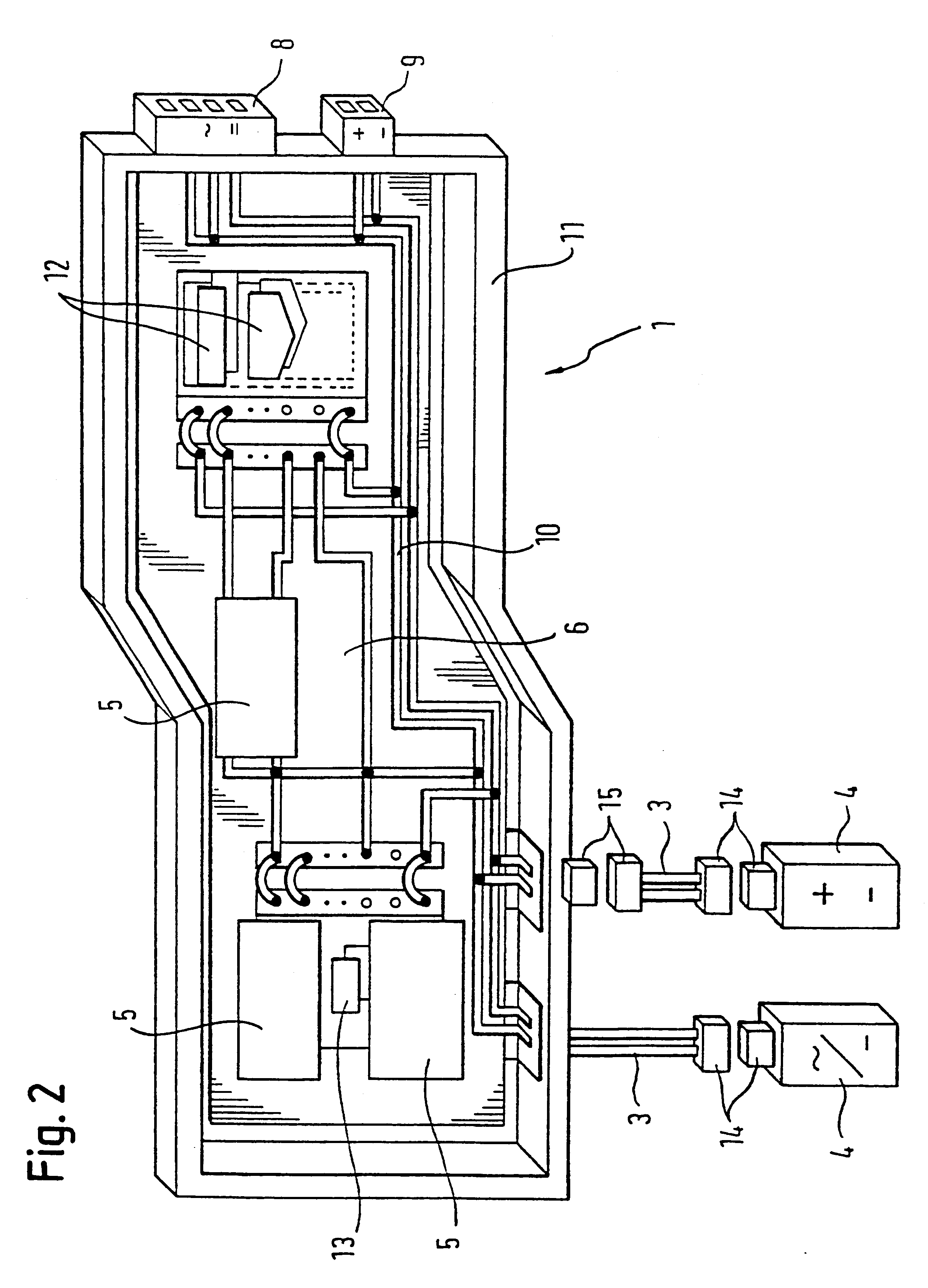
This technical problem is, according to the invention, solved by an electrical wiring system with the features of point-to-point connections. The related circuits of the first and second electrical connections are made within the central distribution unit. This central distribution unit is mounted on the drive unit and comprises a control platform with at least one electronic control module.

Thanks to this wiring concept with a central circuit and electrical point-to-point connections, there are no electrical branches as in the case of the traditional wiring harness. Thus, the cable end connectors, which until now had to be produced at considerable manual effort on the wiring harness, are no longer required. In this respect, ...


PUM


Abstract

The invention relates to an electrical wiring system for the drive unit in automobiles, especially for a combustion engine having a transmission, comprising a central distribution unit (1), first electrical connections (8, 9) between the vehicle and the distribution unit (1), second electrical connections (3) between the distribution unit (1) and the functional units (4) of the drive unit (7) or in the surrounding engine area, wherein the first (8, 9) and the second (3) electrical connections are configured as electrically non-branching point-to-point connections, the interconnections (10) between the first and the second electrical connections are configured in the central distribution unit, the central distribution unit (1) is mounted on the drive unit (7) and the central distribution unit (7) comprises a control platform (6) with at least one electronic control module (5).

Description

The invention relates to an electrical wiring system for the drive unit in vehicles, which will be referred to in the following merely as wiring. The wiring is, in particular, destined for the drive unit, i.e. in particular for the internal combustion engine and transmission of a motor vehicle. It may, however, also be used for motorcycle engines, boat engines or aircraft engines.STATE OF THE ARTHitherto, a wiring harness has been provided in the engine compartment of a motor vehicle, which connects the functional units of the internal combustion engine and other electrical functional units within the engine compartment with each other and with the rest of the vehicle as far as the electrical power supply and the exchange of data and signals is concerned. Such functional units are, in particular, sensors, such as knock or oil level sensors, and actuators, such as injection and ignition means. Apart from electrical wires, wiring harnesses may, in particular, also include optical wire...

Claims


Application Information

Patent Timeline
Patent Type & Authority Patents(United States)
IPC IPC(8): B60R16/02H02G3/00
CPCB60R16/0207H02G3/00
Inventor HENTSCHEL, ANDREASKASPRZOK, MANFREDGROBMAIR, MAXECKSTEIN, FRED
Owner BAYERISCHE MOTOREN WERKE AG
Why Eureka
Try Eureka