Signal detector employing coherent integration

a signal detector and coherent integration technology, applied in direction finders, radio wave direction/deviation determination systems, instruments, etc., can solve the problems of data collection and carrier tracking no longer being possible, the magnitude of noise present in each value accumulates incrementally in the final sum, and the power consumption of the receiver is also dramatically increased

Inactive Publication Date: 2003-06-10
CSR TECH INC
View PDF153 Cites 55 Cited by
  • Summary
  • Abstract
  • Description
  • Claims
  • Application Information

AI Technical Summary

Problems solved by technology

For example, when C / No falls below 26-28 dB-Hz, data collection and carrier tracking are no longer possible, and GPS receivers change to the code track only mode in which is not possible to receive the 50 Hz data streams to derive bit sync.
The problem is that noise which may be and typically is reflected in the product values has a magnitude, and when the product values are added together, the magnitude of the noise which is present in each of the values accumulates incrementally in the final sum due to the non-coherent integration procedure.
In addition, the power consumed by the receiver is also dramatically increased.
The problem is particularly acute for applications involving integrating a GPS receiver with a mobile wireless handset.
The consumption of excessive power by such a device drains battery power, and reduces the call-time available from the handset.
According to the second implementation, these results are non-coherently combined.
A related issue is integrations performed across multiple segments.

Method used


Image

  • Signal detector employing coherent integration
  • Signal detector employing coherent integration
  • Signal detector employing coherent integration

Examples


Embodiment Construction

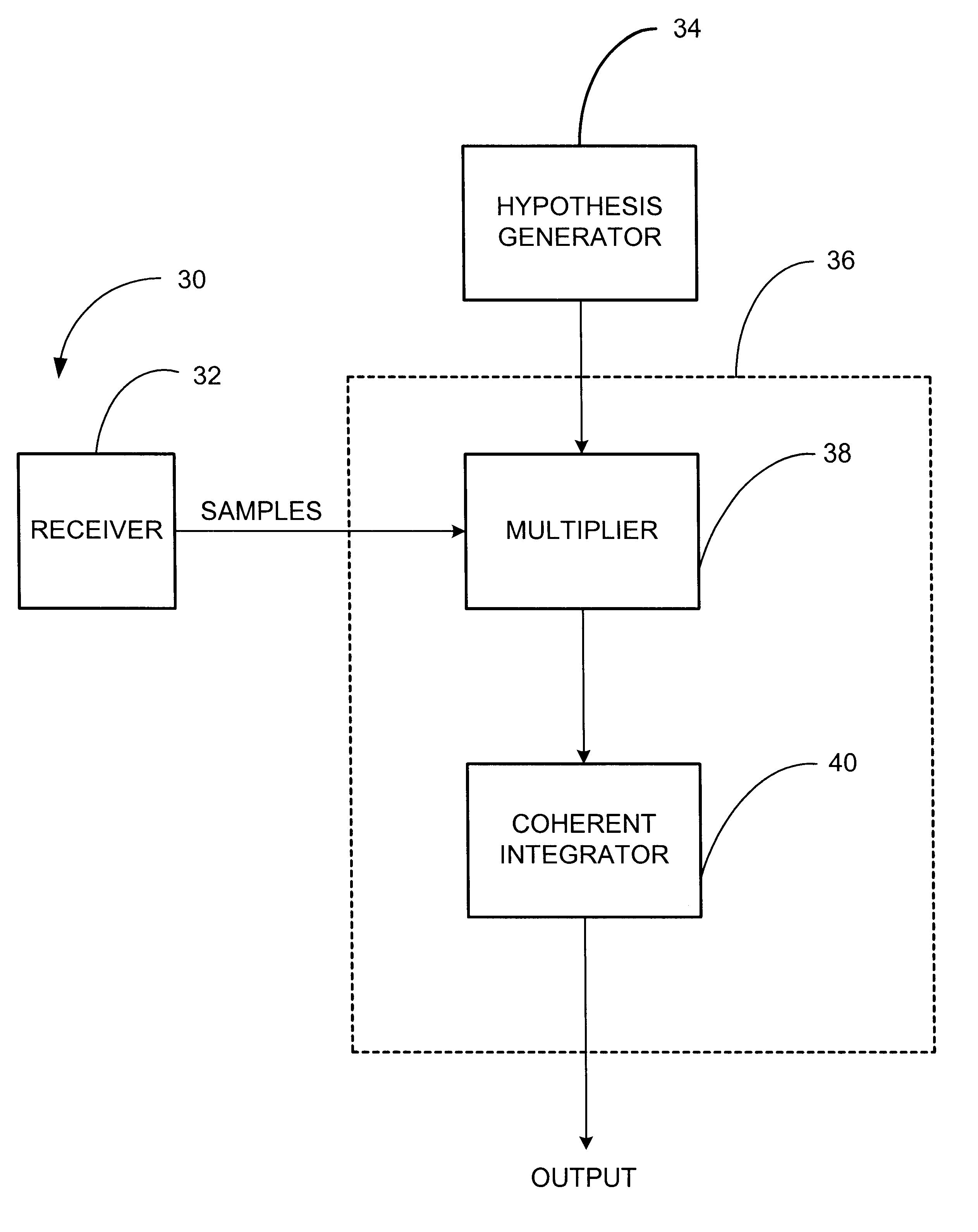
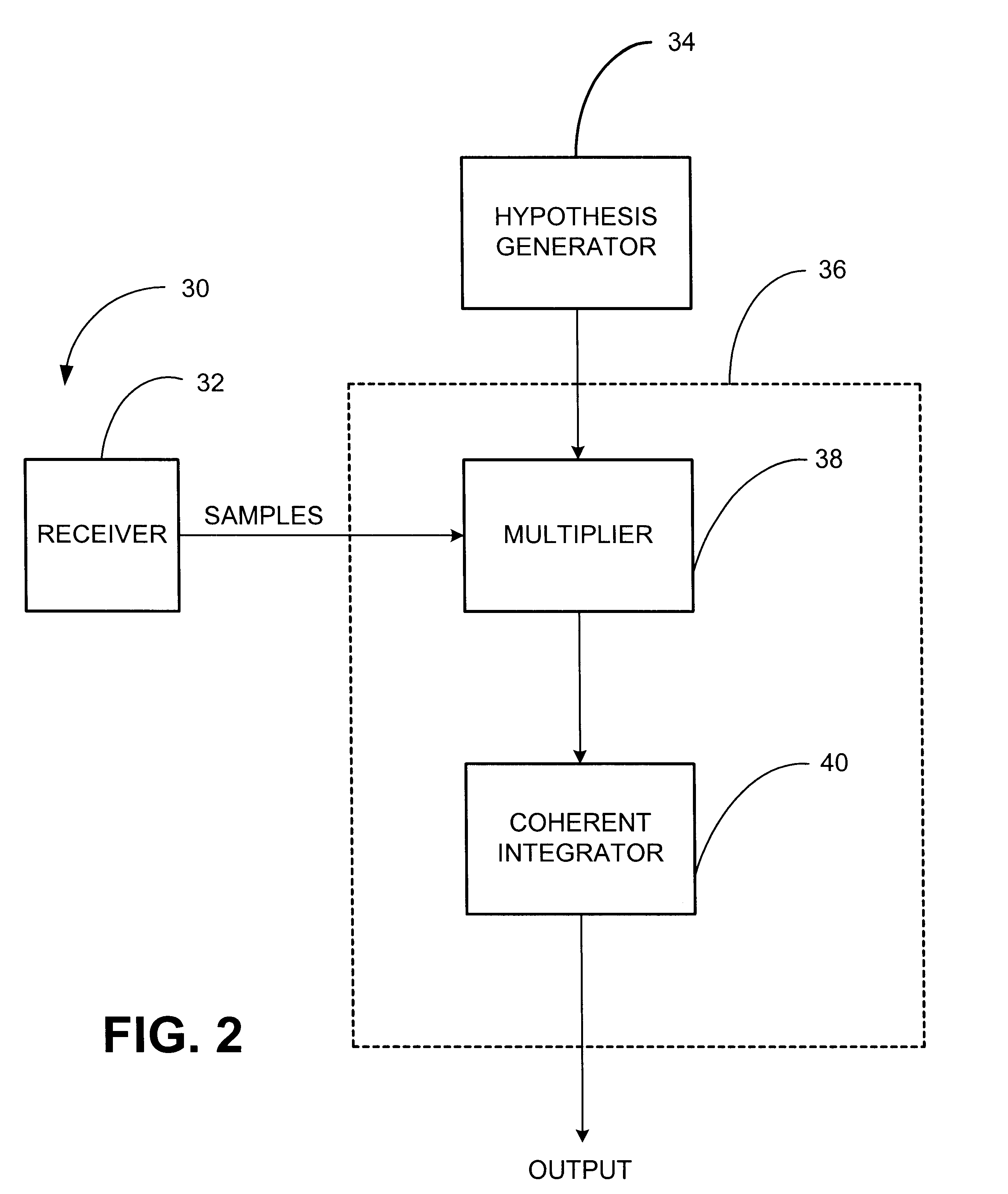
matched filter chip combines selected functionality of the sampling circuitry 308, the timing circuitry 307, and the matched filter 310 of FIGS. 8 and 10. In one implementation, the processor has additional GPS-specific circuits, such as tracking channels for continuously tracking a number of GPS satellite signals. Typically, the processor includes at least an embedded microprocessor with an external bus. In one configuration, the processor views the matched filter chip as a memory mapped peripheral. It issues commands to the matched filter chip, and retrieves results after it has completed processing for a given set of commands. An RF receiver chip embodies the functionality of the GPS radio receiver 300 of FIG. 4. Additional details regarding this implementation example are available in U.S. Pat. No. 6,044,105, and in U.S. Pat. No. 6,304,216, previously incorporated herein by reference.

In order to perform coherent integration over intervals greater than 20 ms, two things are requi...


PUM


Abstract

A signal detector is provided in which complex samples of a received signal are multiplied by data representative of a hypothesis, and the resulting product data is coherently integrated over a desired duration to provide correlation data representative of the level of correlation between the hypothesis and the signal. In one embodiment, the signal detector is part of a GPS receiver.

Description

I. Field of the InventionThis invention relates to the field of signal detection using correlation analysis, and more specifically, to correlation analysis in which coherent integration is employed in order to more rapidly achieve a target signal to noise ratio (SNR).II. Background of the InventionThe Global Positioning System (GPS) is a collection of 24 earth-orbiting satellites. Each of the GPS satellites travels in a precise orbit about 11,000 miles above the earth's surface. A GPS receiver locks onto at least 3 of the satellites, and responsive, thereto, is able to determine its precise location. Each satellite transmits a signal modulated with a unique pseudo-noise (PN) code. Each PN code comprises a sequence of 1023 chips which are repeated every millisecond consistent with a chip rate of 1.023 MHz. Each satellite transmits at the same frequency. For civil applications, the frequency is known as LI and is 1575.42 MHz. The GPS receiver receives a signal which is a mixture of th...

Claims


Application Information

Patent Timeline
Patent Type & Authority Patents(United States)
IPC IPC(8): G01S1/00G01S1/04G01S19/23G01S19/24G01S19/25G01S19/29G01S19/30G01S19/35G01S19/37
CPCG01S19/30G01S19/29G01S1/045G01S19/256
Inventor GRONEMEYER, STEVEN A.
Owner CSR TECH INC
Why Eureka
Try Eureka