Toy comprising interconnected figures having directionally selectable spring-loaded propulsion mechanisms

a propulsion mechanism and interconnected figure technology, applied in the direction of toy figures, hollow non-inflatable balls, self-moving toy figures, etc., can solve the problems of unpredictable angle of ball bounce, user's control of rebound angle, and rapid decline of rebound velocity

Inactive Publication Date: 2003-06-17
MAXIM JOHN G
View PDF9 Cites 23 Cited by
  • Summary
  • Abstract
  • Description
  • Claims
  • Application Information

AI Technical Summary

Problems solved by technology

Intersecting bands or spaced apart bumps made of the same resilient material protrude from the ball spherical surface and cause the ball to bounce at unpredictable angles upon impacting a play surface.
A problem with Hanshaw is that the ball has no stored energy beyond that imparted to it from the force of a throw and from gravity, so that rebound velocity diminishes rapidly.
Another problem is that the user has no control over rebound angles, limiting user involvement, variations in ball use and user interest.
Problems with Kulesza, et al. are that the user has no control over foot propulsion direction, and only one propulsion mechanism is provided so that a sequence of bouncing actions is not produced.
A problem with Weiss is that the lateral positioning of the drive rod to cause the shoulder to engage the radial flange is very slight, and does not materially alter or control the puppet jumping direction.
Another problem is that only one propulsion mechanism is provided, and thus no entertaining sequence of jumps is disclosed.
Still another problem is that the spring does not overlap or enter the piston, so that the propulsion mechanism bore must be quite deep.
While this ball produces a random and generally unpredictable bouncing motion, the cost of its manufacture with the internal mechanism limits the product to a relatively high-end market.
A problem with Sonesson is that the user cannot select and pre-set rolling directions.
Another problem is that the shifting of the center of gravity does not release stored ball propelling energy to the ball as it moves, limiting the play time for each roll.
Still another problem is that no entertaining jumping action is produced.
A problem with Lacey is that the user cannot select and pre-set the directions of ball propulsion.

Method used


Image

  • Toy comprising interconnected figures having directionally selectable spring-loaded propulsion mechanisms
  • Toy comprising interconnected figures having directionally selectable spring-loaded propulsion mechanisms
  • Toy comprising interconnected figures having directionally selectable spring-loaded propulsion mechanisms

Examples


Embodiment Construction

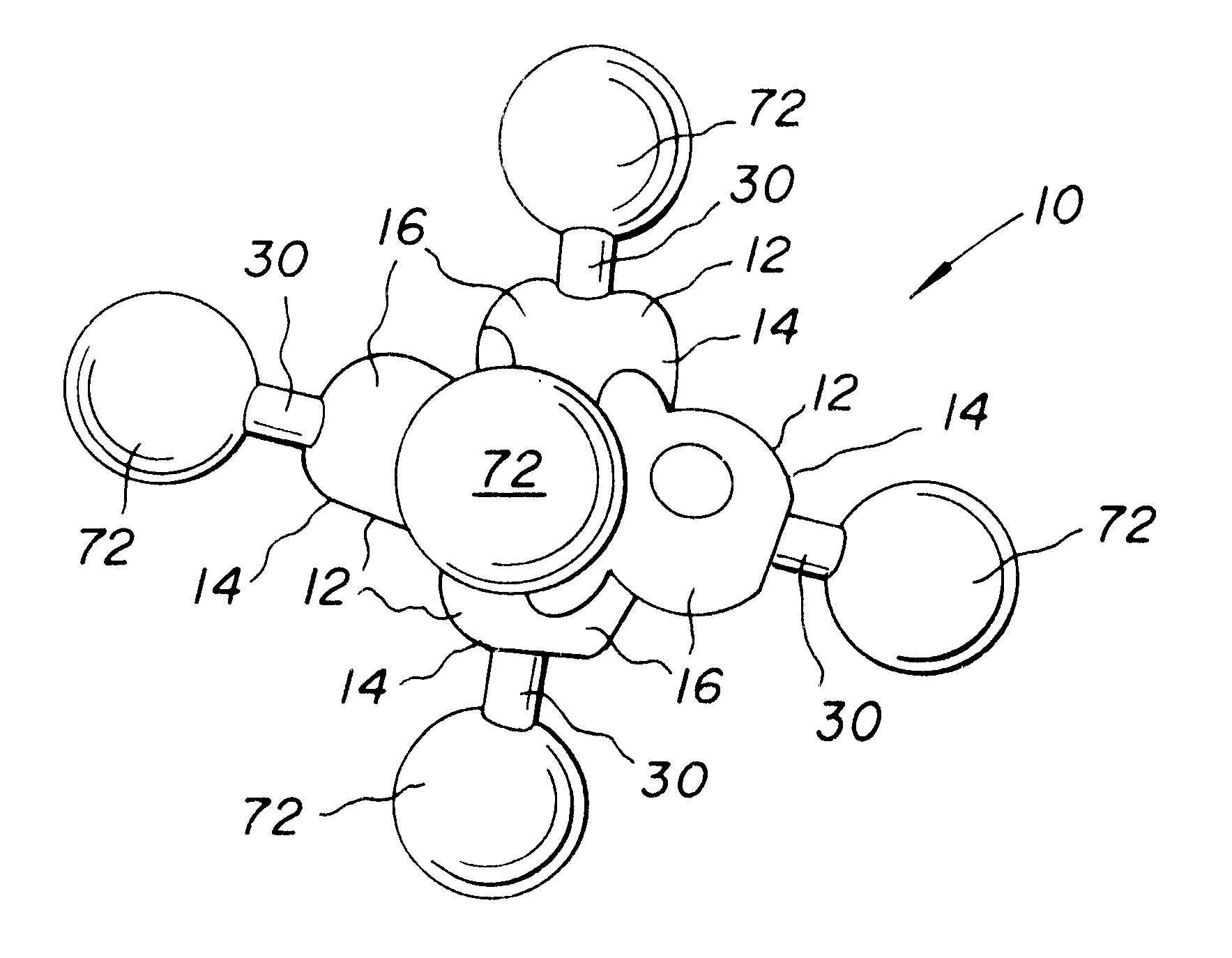
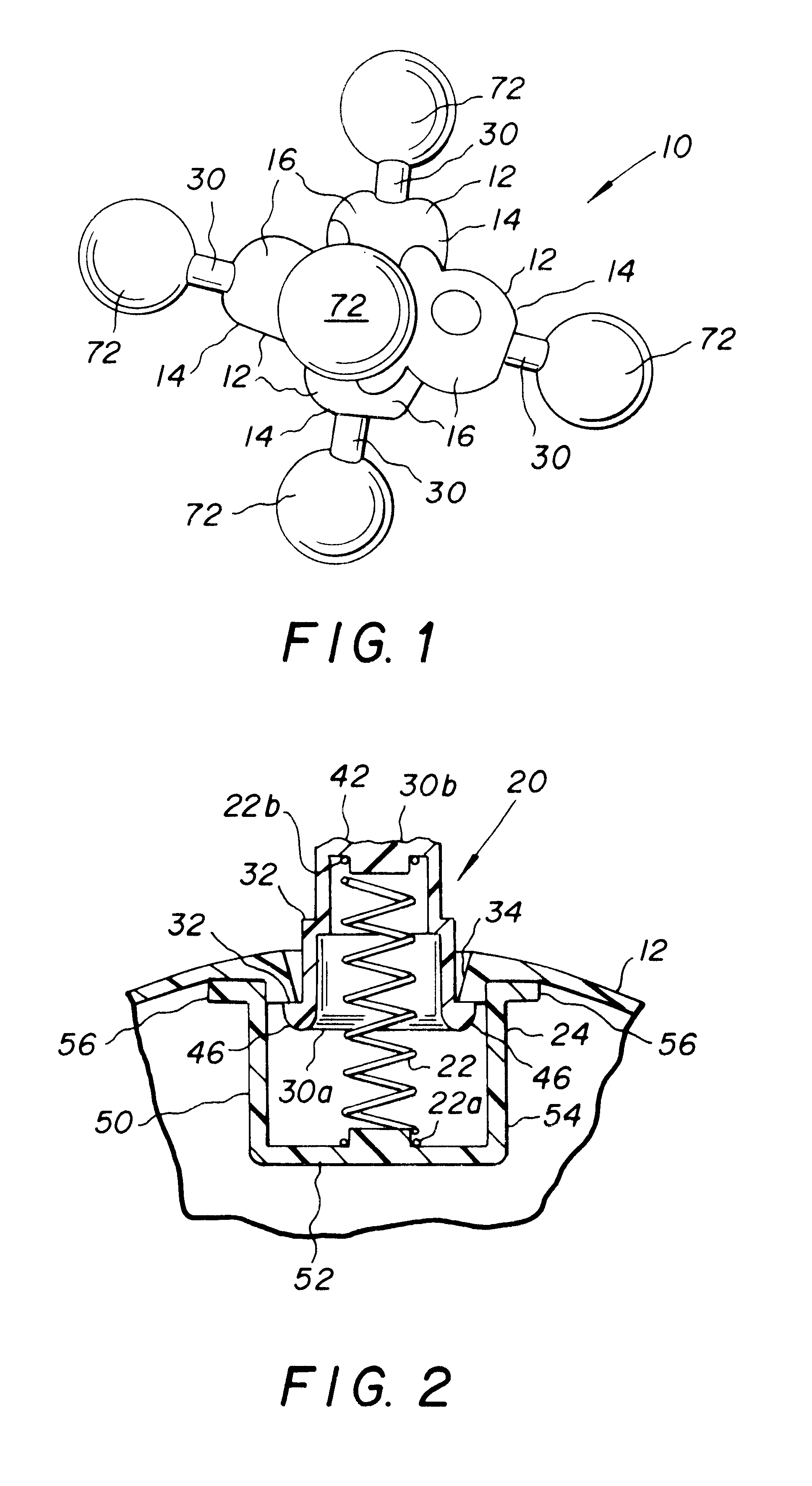
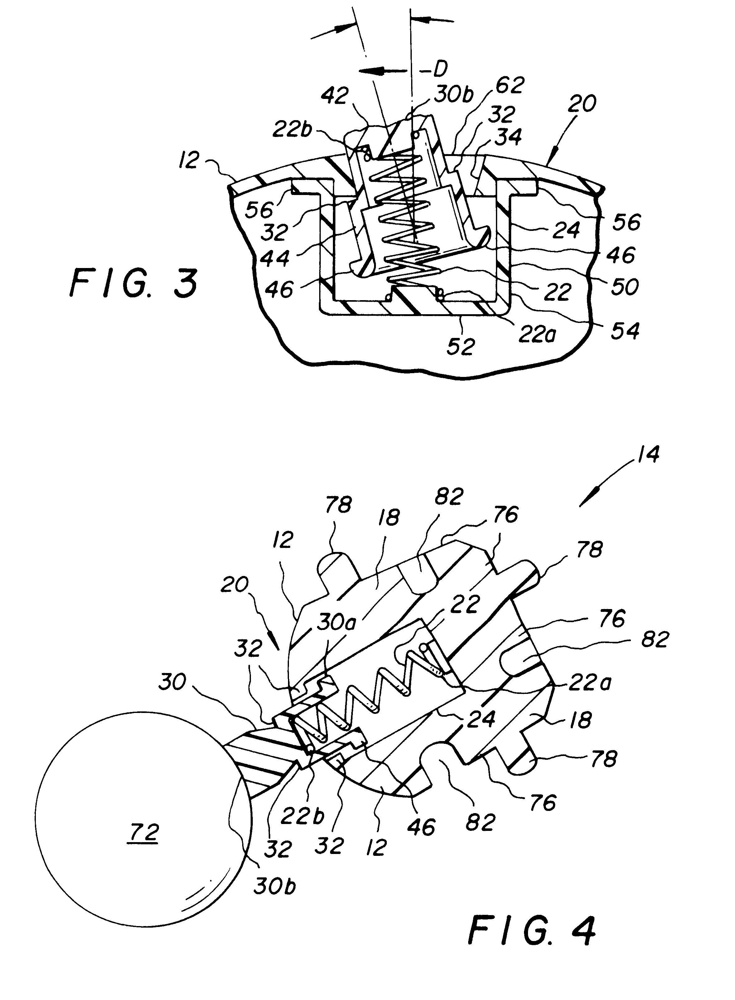
Referring to FIGS. 1-4, a toy 10 is disclosed including several separably interconnected structure elements 14 defining a composite structure 16, each structure element 14 including a spring-loaded, directionally selectable propulsion mechanism 20. The structure element 14 includes a element shell 12 including a shell interconnection portion having a shell interconnection structure 18 and a shell propulsion portion having the propulsion mechanism 20.

Each propulsion mechanism 20 includes a coil spring 22 secured at a spring base end 22a to the element shell 12 and at a spring free end 22b to a projection member 30. The projection member 30 has an outwardly extending contact end 30b and an inwardly directed stop end 30a and has a circumferential shoulder 32 between the contact end 30b and the stop end 30a. The contact end is preferably fitted with a resilient ball. The projection member 30 protrudes between opposing and spaced apart shoulder engaging structures 34 in the shell propuls...


PUM


Abstract

A toy for entertaining a user includes a composite structure configured to execute a play function, the composite structure including several removably interconnected structure elements, each said structure element having at least one propulsion mechanism including a spring-loaded, directionally selectable propulsion member connected to the structure element. The triggering object is optionally a play surface and the element shell optionally includes a representation of a human or animal face. The composite structure has at least two of the structure elements, each structure element having a propulsion mechanism so that several propulsion mechanisms are distributed over the outer extremities of the composite structure for depressing and tilting by the user in individually selected directions into engagement with the shoulder engaging structure.

Description

1. Field of the InventionThe present invention relates generally to the field of toys animated by energy-storing mechanisms. More specifically the present invention relates to a toy including several separably interconnected figure elements defining a composite structure, each figure element including a spring-loaded, directionally selectable propulsion mechanism. The figure element includes a element shell including a shell interconnection portion having a shell interconnection structure and a shell propulsion portion having the propulsion mechanism.Each propulsion mechanism includes a coil spring secured at a spring base end to the element shell and secured at a spring free end to a projection member. The projection member has an outwardly extending contact end and an inwardly directed stop end and has a circumferential shoulder between the contact end and the stop end. The projection member protrudes between opposing and spaced apart shoulder engaging structures in the shell prop...

Claims


Application Information

Patent Timeline
Patent Type & Authority Patents(United States)
IPC IPC(8): A63H11/00A63H11/06A63B43/00
CPCA63B43/00A63H11/06A63B2208/12
Inventor MAXIM, JOHN G.
Owner MAXIM JOHN G
Why Eureka
Try Eureka