Mist feeder

Inactive Publication Date: 2003-07-15
KURODA PRECISION INDS
View PDF4 Cites 6 Cited by
  • Summary
  • Abstract
  • Description
  • Claims
  • Application Information

AI Technical Summary

Benefits of technology

It is another object of the invention to provide a mist supply apparatus, in which a mist pressure can be maintained at a given value or can be increased temporarily.
It is still another object of the present invention to provide a mist supply apparatus which can supply a mist with a suitable concentration.

Problems solved by technology

In either cases, since the liquid oil is sprayed to a working site, a large amount of oil spreads around the working site.
This results in an undesired waste of oil and a serious problem of environment pollution.
Moreover, even though the oil is cooled, bacillus might be produced in the oil and the oil might be subjected to contamination and corrosion.
This results in that an amount of mist actually supplied to the working site becomes smaller than a total amount of supplied mist.
In this manner, the work piece is stained with oil and the environment pollution might occur.
Furthermore, since a given amount of oil is supplied by the reciprocal pump in an intermittent manner, when a large amount of oil is sprayed abruptly, an excess amount of oil could not be converted into a mist, and liquid oil might be circulated.
Therefore, the known mist supply apparatus could not be effectively applied to machine tools for drilling deep holes and tapping.

Method used


Image

  • Mist feeder
  • Mist feeder
  • Mist feeder

Examples


first embodiment

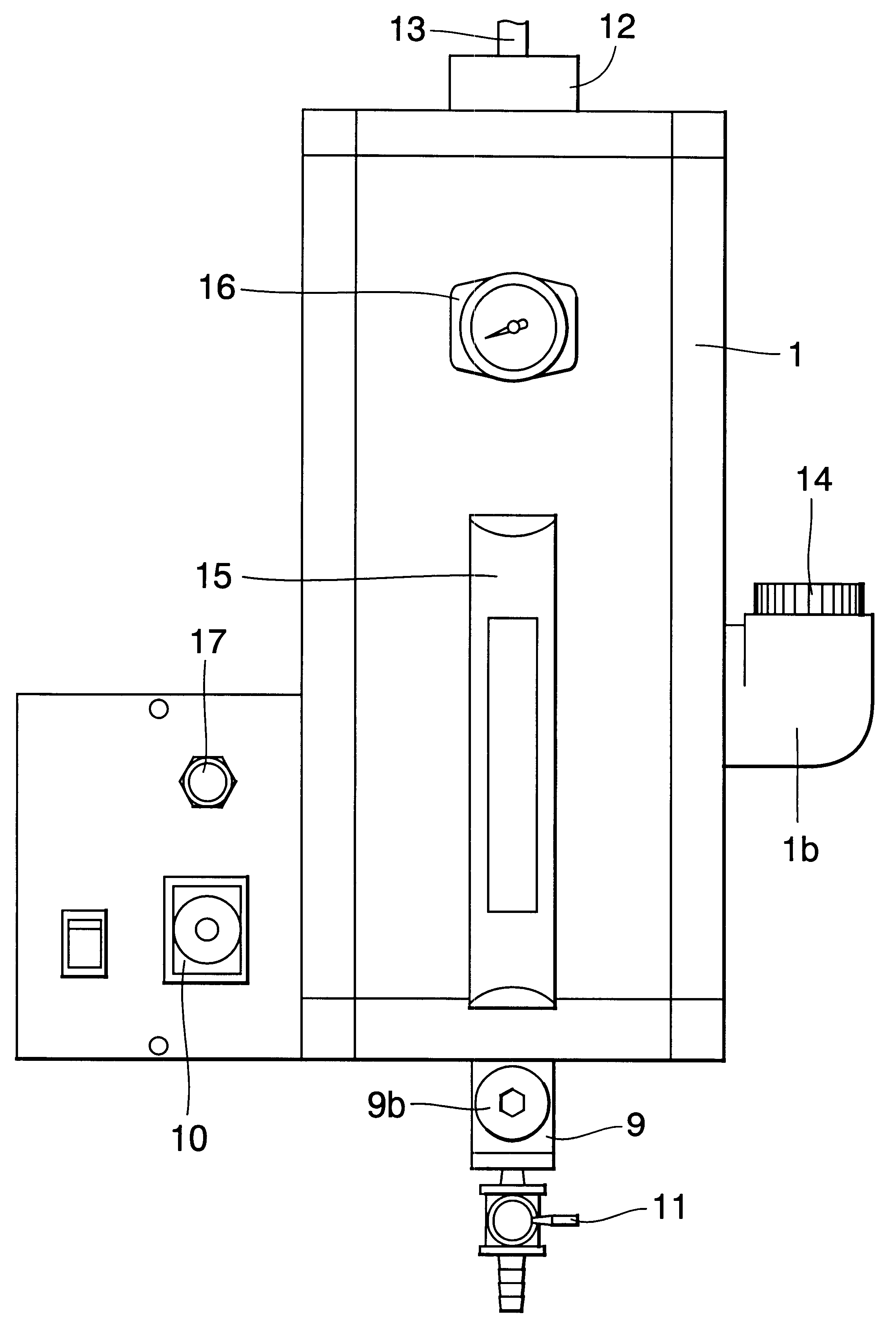
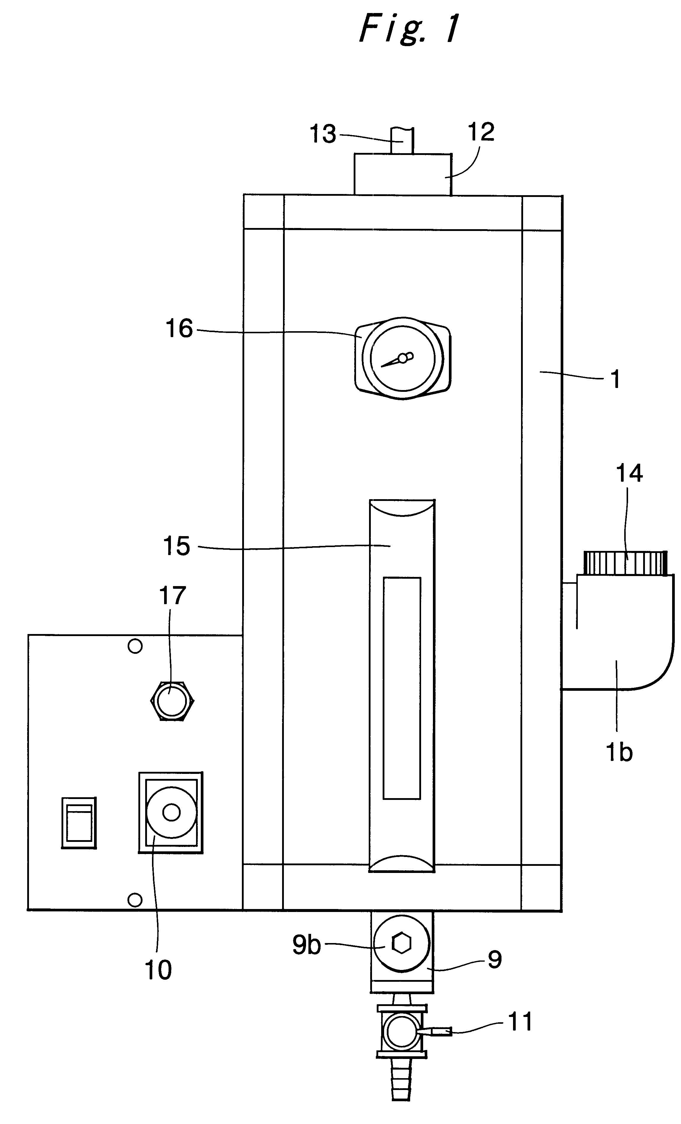
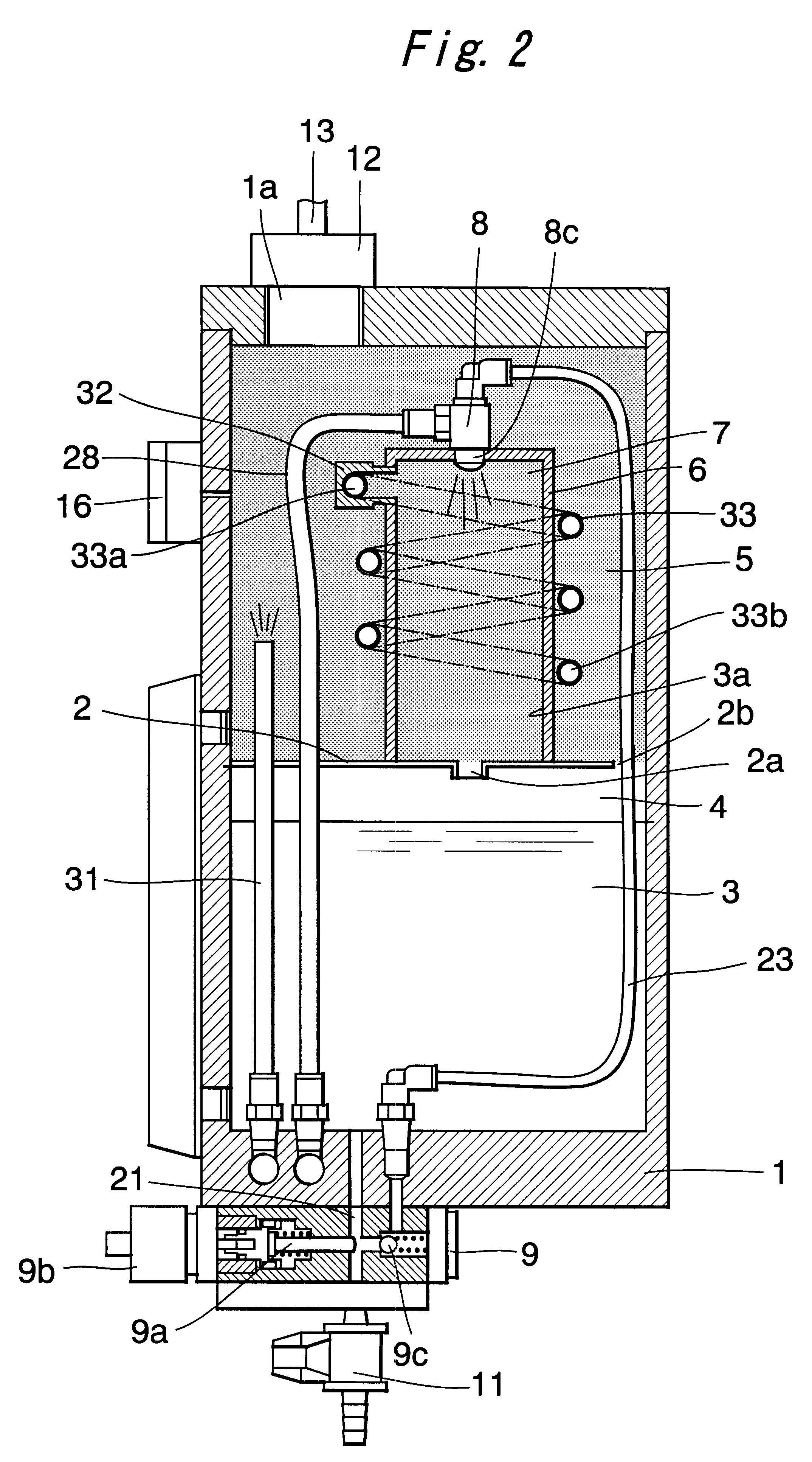
FIG. 1 is a front view of the mist supply apparatus according to the invention, and FIG. 2 is a longitudinal cross section thereof. An inner space of a main tank 1 having a substantially rectangular cylindrical shape is divided into upper and lower spaces by means of a partition plate 2. The upper space constitutes an oil chamber 4 containing an oil 3, and the upper space constitutes a main mist chamber 5. In the partition plate 2, there are formed a through hole 2a at a center and conduit holes 2b at a periphery. On the partition plate 2 is arranged an inner tank 6 at a center of the partition plate. An inner space of the inner tank 6 is communicated with the through hole 2a and constitute an inner mist chamber 7. At a top ceiling of the inner tank 6, there is provided a spray nozzle 8 for converting the oil 3 into mist with the aid of a compressed air.

On an outer surface of a bottom of the main tank 1, there is arranged a pump 9 for supplying the oil 3 into the spray nozzle 8. The...

second embodiment

In this manner, in the second embodiment, since the mist supply pressure from the tool 43 is controlled into a given value by introducing the compressed air from the compressed air supply source 24 into the main mist chamber 5 by means of the pressure control valve 53, although a diameter of the mist conduit 44 formed in the tool 43 is changed in accordance with the exchange of the tool in the machine tool 40, the mist can be sprayed from the tool 43 under a given pressure. Therefore, the good cooling faculty and lubrication faculty can be maintained, and the faculty for removing cut chips or debris is not lost.

It should be noted that in the second embodiment, the pressure is supplied from the main mist chamber 5 into the pressure control valve 53 by means of the pilot conduit 55, but the pressure control resembling much more the actual variation in the mist pressure can be performed by introducing the pressure from the mist conduit 13 via a pilot conduit 55' as illustrated in a par...

third embodiment

In the third embodiment, upon removing the cut chips after treating the word W, its command signal is supplied to the second reducing valve 80 and the compressed air in the pilot conduit 55 is discharged into the atmosphere. Then, the pressure control valve 53 is driven into the full-open state, and the compressed air from the compressed air supply source is introduced into the inner mist chamber 7. Therefore, the pressure inside the inner mist chamber 7 and main mist chamber 5 is increased abruptly to increase an amount of mist sprayed from the tool 43.

FIG. 13 is a cross sectional view illustrating a pressure control valve 53" used in a modification of the above mentioned third embodiment. To the pressure control valve 53 used in the third embodiment shown in FIG. 12, there are added a pressure difference producing spring 76 for generating a pressure difference by biasing the diaphragm 70 toward the pressure adjusting spring 73. A bias force of the pressure difference producing spr...


PUM


Abstract

An inner tank 6 is arranged on a partition plate 2 in a main tank 1, and a spray nozzle 8 is provided in a top wall of the inner tank 6. A mist separator 33 is formed by a helical tube wound around an outer wall of the inner tank 6. An upper port 33a of the mist separator 33 is connected to a connector block 32 provided at an upper portion of the inner tank 6 and a lower port 33b is positioned at a lower portion of a main mist chamber 5. Smaller particles in a primary mist produced by the spray nozzle 8 float in an upper portion of an inner mist chamber 7. Larger particles in the primary mist descend toward a lower portion of the inner mist chamber 7, and these particles adhere onto an inner wall of the inner tank 6 to form a secondary mist consisting of the smaller particles. The secondary mist is subjected to acceleration and centrifugal force during a passage through the mist separator 33, where the larger particles in the secondary mist adhere onto an inner wall of the mist separator, and the main mist chamber is filled with a tertiary mist consisting of smaller particles.

Description

The present invention relates to a mist supply apparatus for supplying mist which may be used for lubricating and cooling a working point or working site in a machine tool.TECHNICAL BACKGROUNDIn general, when a work is treated by a machine tool, it is necessary to spray or eject a large amount of oil to a working site for lubrication and cooling. In this case, the oil is sprayed to a working site by means of oil conduits formed within a main spindle of a machine tool and a tool or the oil is directly sprayed to a working site without being passed through the oil conduits.In either cases, since the liquid oil is sprayed to a working site, a large amount of oil spreads around the working site. This results in an undesired waste of oil and a serious problem of environment pollution. In general, the oil is reused by circulation and therefore it is necessary to provide an oil cooling means in a circulation path. Moreover, even though the oil is cooled, bacillus might be produced in the o...

Claims


Application Information

Patent Timeline
IPC IPC(8): F16N39/00F16N7/32F16N7/00F16N39/06F16N7/34
CPCF16N7/32F16N7/34F16N39/06B23Q11/1084B23Q11/10
Inventor NATSU, WATARUKAMIMA, TAKESHI
Owner KURODA PRECISION INDS
Why Eureka
Try Eureka