Underwater pipe laying method and apparatus

a technology of pipelines and laying methods, applied in the direction of pipe laying and repair, cable laying vessels, pipe laying and other directions, can solve the problems of not allowing the insertion of such items in the pipeline, the existing pipe laying system in the tower does not allow the convenient handling of such a bulky device, and the tension applied to the pipeline is temporarily loosening

Inactive Publication Date: 2003-07-15
HEEREMA MARINE CONTRACTORS NEDERLAND SE
View PDF17 Cites 50 Cited by
  • Summary
  • Abstract
  • Description
  • Claims
  • Application Information

AI Technical Summary

Benefits of technology

The method and apparatus of the present invention also permits a pipe section to be added to a pipeline more rapidly than the heretofore utilized pipe laying systems, such as shown in U.S. Pat. No. 5,421,675 since it eliminates the necessity that the strongback support a pipe section while the latter is welded to the pipeline.

Problems solved by technology

However, where large or bulky devices must be inserted into the pipeline, these systems do not permit expedient insertions of such items in the pipeline.
Existing pipe lay systems in the tower do not allow convenient handling of such a bulky device, since it is not practical to design a fixed pipe clamping mechanism which will open up sufficiently wide as to permit downward passage of such devices.
Also, where the pipeline extends through a plurality of tensioners it is necessary to successively open such tensioners to permit passage of such bulky devices thereby temporarily loosening tension applied to the pipeline.

Method used


Image

  • Underwater pipe laying method and apparatus
  • Underwater pipe laying method and apparatus
  • Underwater pipe laying method and apparatus

Examples


Embodiment Construction

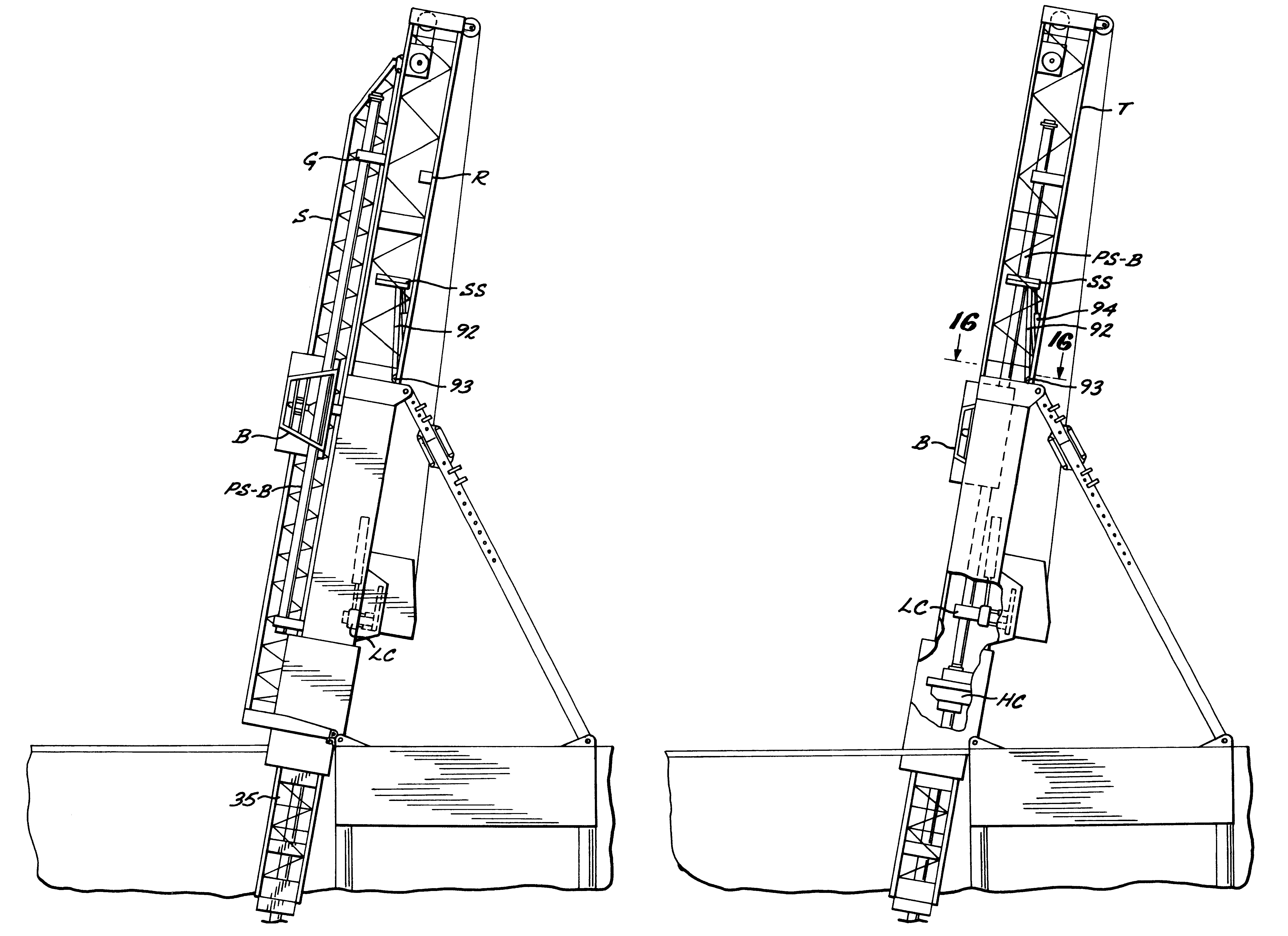
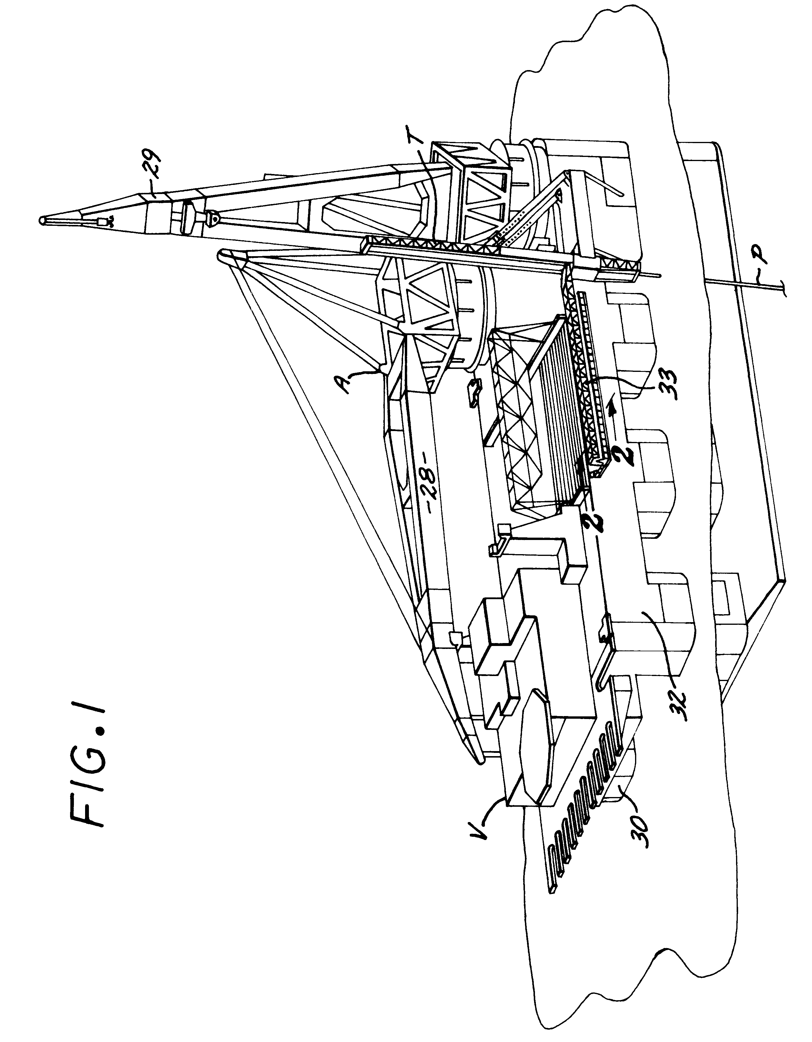
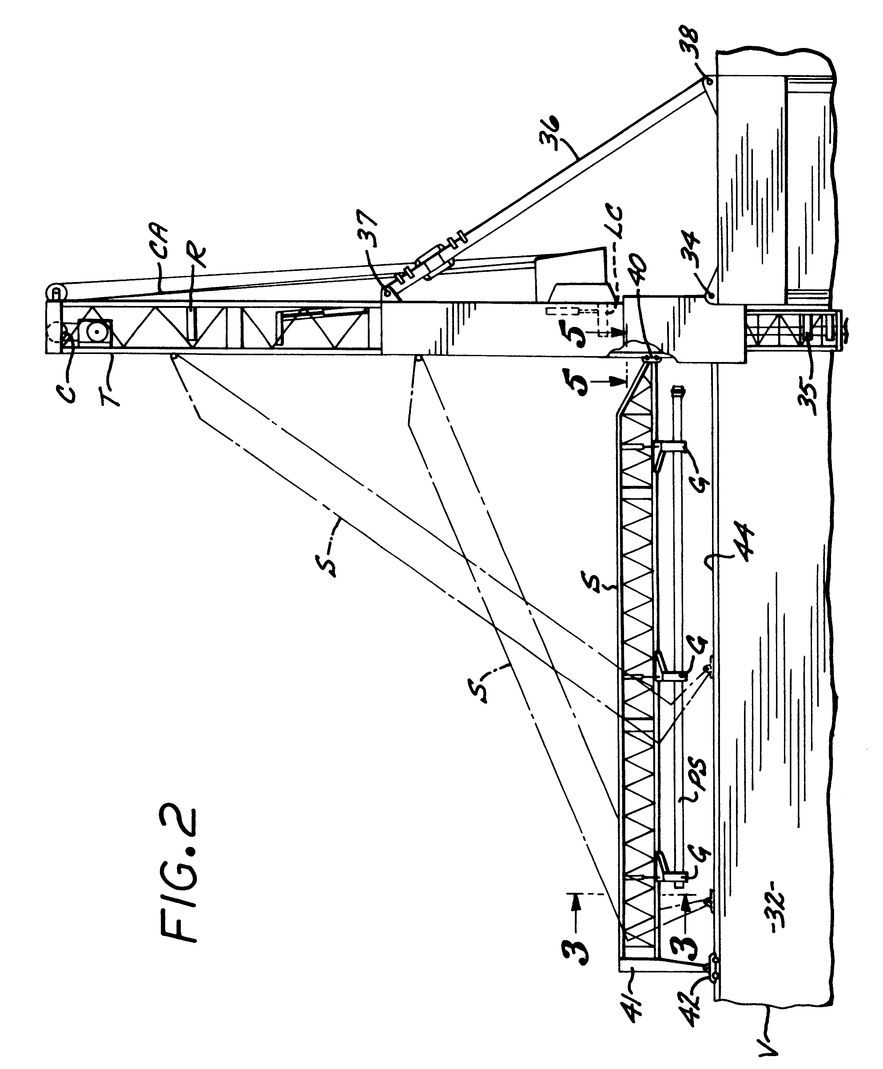
Referring to the drawings, a pipe laying vessel V, shown in FIG. 1, is provided with a first preferred form of apparatus A for the underwater laying of a pipeline P on a seabed (not shown). Vessel V is of the semi-submersible type, however, other types of vessels may be utilized for operation with pipe laying apparatus of the present invention. Vessel V is provided with two large rotatable cranes 28 and 29 of conventional construction mounted at the rear end portions of the semi-submersible hulls 30 and 32. Vessel V carries a supply of pipe sections 33 on its deck to be added to pipeline P. With further reference to FIG. 1 and also to FIG. 2, the pipe laying apparatus A includes a J-Lay tower T pivotally connected at 34 to vessel V for tilting in a vertical plane by hydraulic cylinders in a conventional manner, with the angle of such tower being defined by adjustable struts 36 having their upper end pivotally attached to the intermediate portion of the tower at 37 and its lower end ...


PUM


Abstract

A method and apparatus for near vertical laying of a pipeline offshore by a pipe laying vessel includes a tower to which is attached a strongback that load pipe sections from a supply point on the vessel into the tower where the lower end of the pipe section is welded onto the upper end of a pipe line that extends into the sea while the strongback returns to the supply point for a second pipe joint. Where the pipe section includes a bulky item such as a valve assembly box, after the pipe section has been welded to the pipeline the pipe section is moved generally horizontally out of the tower and a hoisting cable lowers the pipe section to a predetermined depth below the tower. The hoisting cable then returns the pipe section and attached pipeline to their original position.

Description

1) Field of the InventionThe present invention is generally related to the underwater laying of pipelines and more particularly to the near vertical laying of pipeline offshore in deep water.2) General BackgroundAt the present time the offshore pipeline industry utilizes the concept of near vertical pipe laying (called J-Lay) as a system for deep water pipe laying. It has been heretofore proposed to conduct J-Lay pipe laying from a vessel having a tower pivotally mounted to the vessel so that it can be stowed horizontally and raised to a near vertical position during a pipe laying operation. A supply of pipe sections is stowed on the vessel's deck. Individual pipe sections are successively positioned within the tower by means of a loader termed a strongback. The strongback holds a pipe section to be introduced into the upper end of a pipeline while the lower end of such pipe section is welded to the upper end of the pipeline. The upper end of the pipeline extends through a fixed tow...

Claims


Application Information

Patent Timeline
Patent Type & Authority Patents(United States)
IPC IPC(8): F16L1/12F16L1/19
CPCF16L1/19F16L1/207F16L1/23
Inventor FRIJNS, TOM LAURENT HUBERTDE GROOT, ANNE KLAAS
Owner HEEREMA MARINE CONTRACTORS NEDERLAND SE
Why Eureka
Try Eureka