Traditional practice calls for use of a hand-held utility-type knife which is slow and inaccurate and potentially dangerous since some types of shingles need multiple passes and considerable force with the knife, which can and does slip, causing injury.
Several designs have been proposed for an apparatus to cut shingles, however, these designs are limited in performance in various ways.
The underlying problem is that shingles
resist being cut, and particularly, cut neatly.
In
cold weather, shingles are stiff and brittle, resistant to cutting, and tend to crack without careful handling.
In
hot weather, they become exceedingly soft and pliable and prone to tearing.
Under any weather conditions, debris and granules from the surface of the shingles are dislodged in handling and collect within the workings of an apparatus not designed to tolerate them.
If the apparatus moves or tips in use, it will be inconvenient or dangerous to use.
Prior art fails to overcome these difficulties and therefore has not met with practical success.
Considered analysis indicates that in addition to this limitation these two designs do not allow the user to develop sufficient leverage to operate successfully under the wide range of
field conditions previously mentioned.
The blade does not consistently maintain tight contact with the edge of the work surface because of lack of sufficient rigidity both of the blade and of the pivot arrangement.
Use of a precision bearing as proposed by Hile has a drawback in that it will be vulnerable to damage in the real-world conditions that prevail while roofing is being done.
This type of work is frequently carried out under wet conditions; also, the tendency of shingles to generate debris particles and shed granules as previously mentioned will degrade a precision mechanism.
Moreover, the need for a complex bearing in this application is questionable, since the motion anticipated is comparatively slow and sporadic and covers something less than a ninety degree arc, whereas a ball or
roller bearing would be more appropriately specified in an application having greater or continuous motion and / or higher speed.
This reduces the accuracy of the cut.
The Hile apparatus also lacks the ability to make an accurate and repeatable angle cut.
Further, there is no provision at all to produce the lengthwise cuts that are necessary for the lowest, or starting course of shingles.
In addition, the fact that the
handle extends substantially beyond the ends of the legs would tend to cause the opposite, or pivot, end of the apparatus to lift in response to the cutting
stroke.
Further, the apparent width between the legs of the apparatus would seem to preclude its use on the narrow scaffolding typically used on a roof.
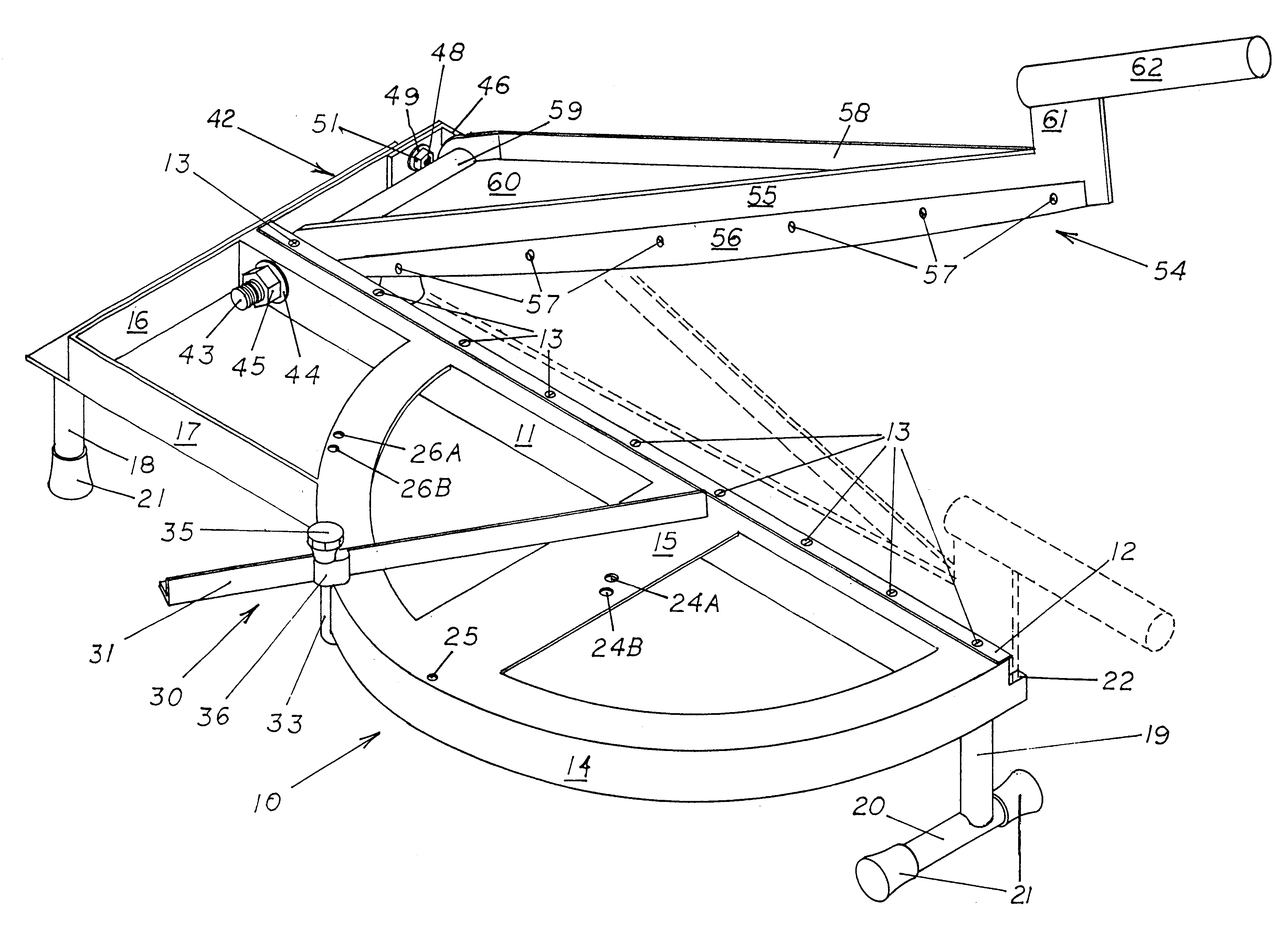
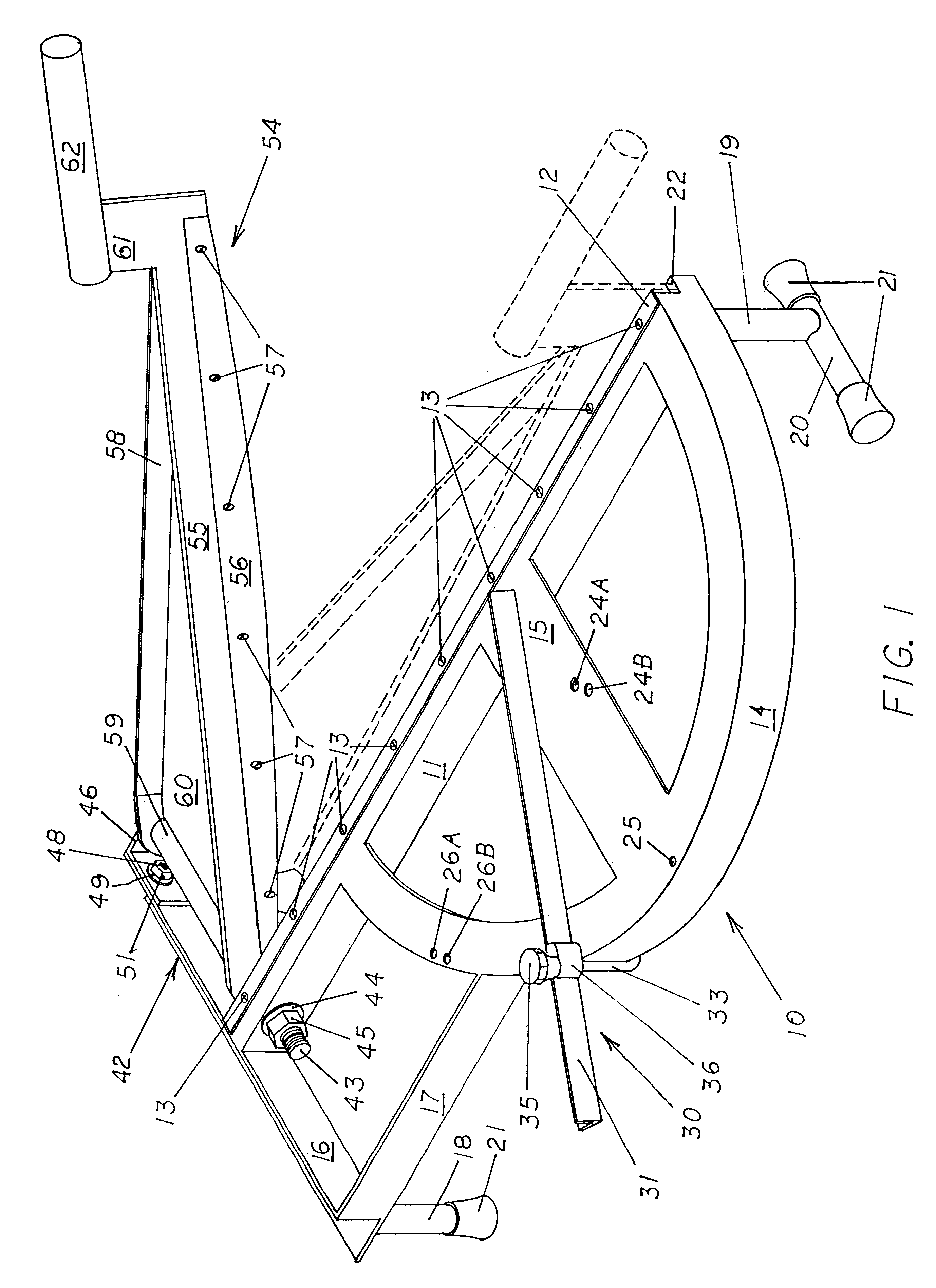
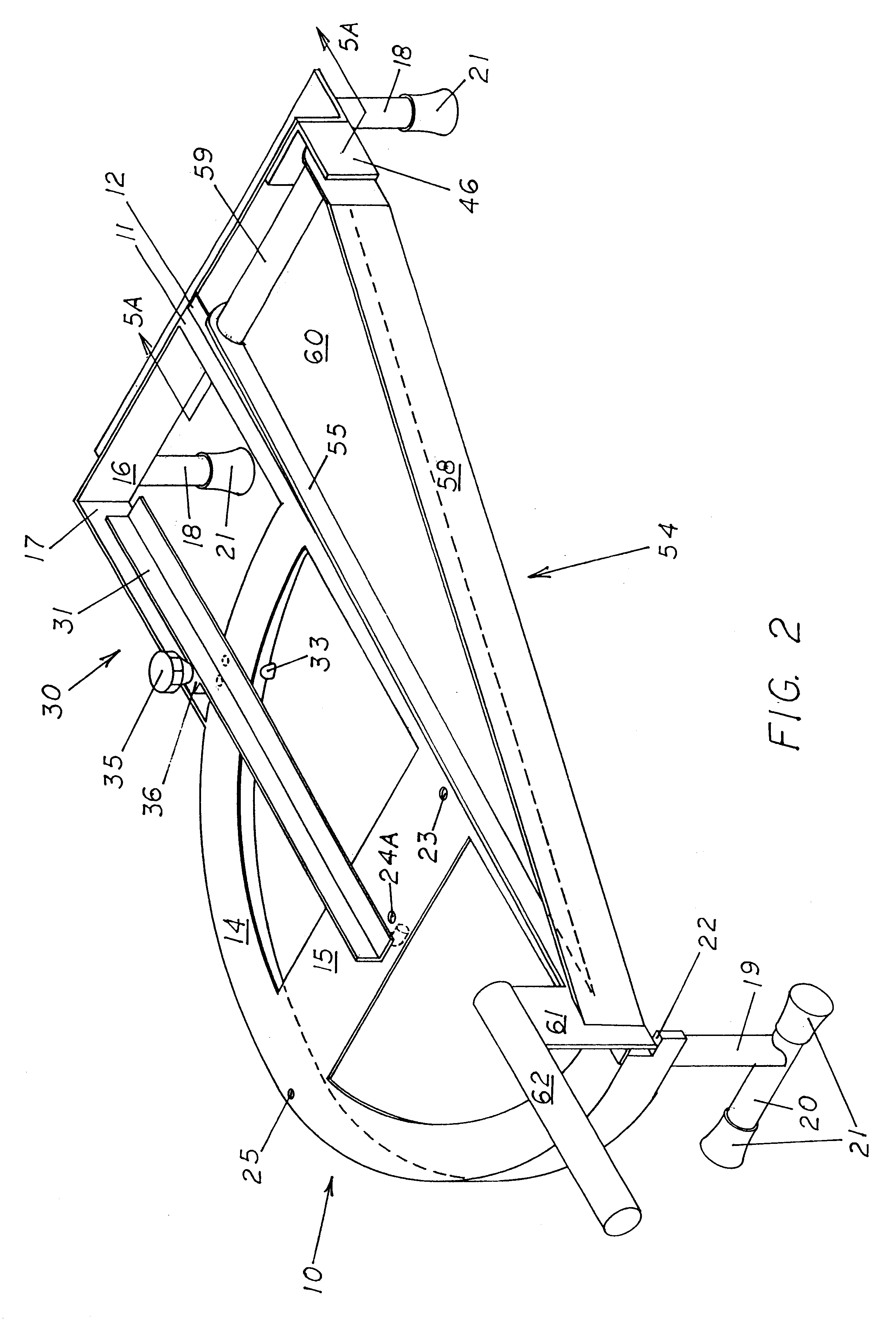
1. The triangular design of the moveable blade assembly, the use of a long pivot shaft attached on both ends, and the design of the frame all provide superior rigidity and keep the moveable and fixed blades in tight contact with each other resulting in clean shearing action. Adjustment is provided to maintain this relationship and to compensate for wear and
sharpening.
2. The moveable blade is prevented from distorting by the combination of the blade brace and the triangular web between them that together form a rigid blade assembly.
3. The use of a vertical moveable blade and a horizontal, protruding fixed blade minimizes tarry buildup since the fixed blade acts as a scraper to keep the moveable blade substantially clean. Since this buildup occurs mainly on wide surfaces, the edge of the fixed blade also remains substantially clean.
4. The use of a fixed blade that protrudes beyond the side of the work surface provides clearance for the shingle cutoff, or waste piece, to curl downward during the cut and fall away without dragging on the side of the work surface, which would force the shingle out of position during the cutting
stroke.
5. The use of a moveable guide fence permits accurate and repeatable angled or ninety degree cuts. A
detent arrangement provides a positive stop for ninety degree cuts.
6. With the guide fence supporting the edge of the shingle furthest from the pivot shaft, the shingle is prevented from sliding in response to the action of the blade. In my apparatus the action of the blade tends to hold the shingle more securely against the guide fence.
7. The guide fence is easily repositioned on the work surface to permit length-wise cutting of shingles. A
detent arrangement positively locates the guide fence parallel to the blades and automatically produces proper width cut pieces in accordance with the several standard dimensions used by shingle manufacturers.
8. The design of the pivot shaft minimizes the accumulation of shingle debris land granules that would inhibit proper operation of the moveable blade. The open end of the blade tube extends under the protruding fixed blade to deflect falling debris. More importantly, there is no precision ball or
roller bearing mechanism that would be vulnerable to infiltration of debris as well as inflitration of
moisture which would create
rust. By eliminating a precision bearing, a potential maintainance problem due to
rust or
contamination is avoided and the apparatus will be simplified.
9. The design of the rear leg enables the user to anchor the device with his or her foot while operating the apparatus if desired. At the same time, the user's foot is protected from injury since it is shielded by the raised frame.

