Multi-phase compensated spinner flow meter

a flow meter and multi-phase technology, applied in the field of formation fluid evaluation, can solve problems such as errors introduced due to the effect of multi-phase compensation

Inactive Publication Date: 2003-08-05
BAKER HUGHES INC
View PDF6 Cites 26 Cited by
  • Summary
  • Abstract
  • Description
  • Claims
  • Application Information

AI Technical Summary

Problems solved by technology

Often, one or more of these phases is an undesired element in the well production flow.
For example, in the case of a well fluid flow regime consisting of oil and water, the oil is typically the fluid phase desired to be produced and the water is typically an undesired phase in the production flow.
By not sensing the fluid type of the same fluid that is intercepted by the spinning element, errors have been introduced due to the inhomogeneities of the multi-phase fluid.

Method used


Image

  • Multi-phase compensated spinner flow meter
  • Multi-phase compensated spinner flow meter
  • Multi-phase compensated spinner flow meter

Examples


Embodiment Construction

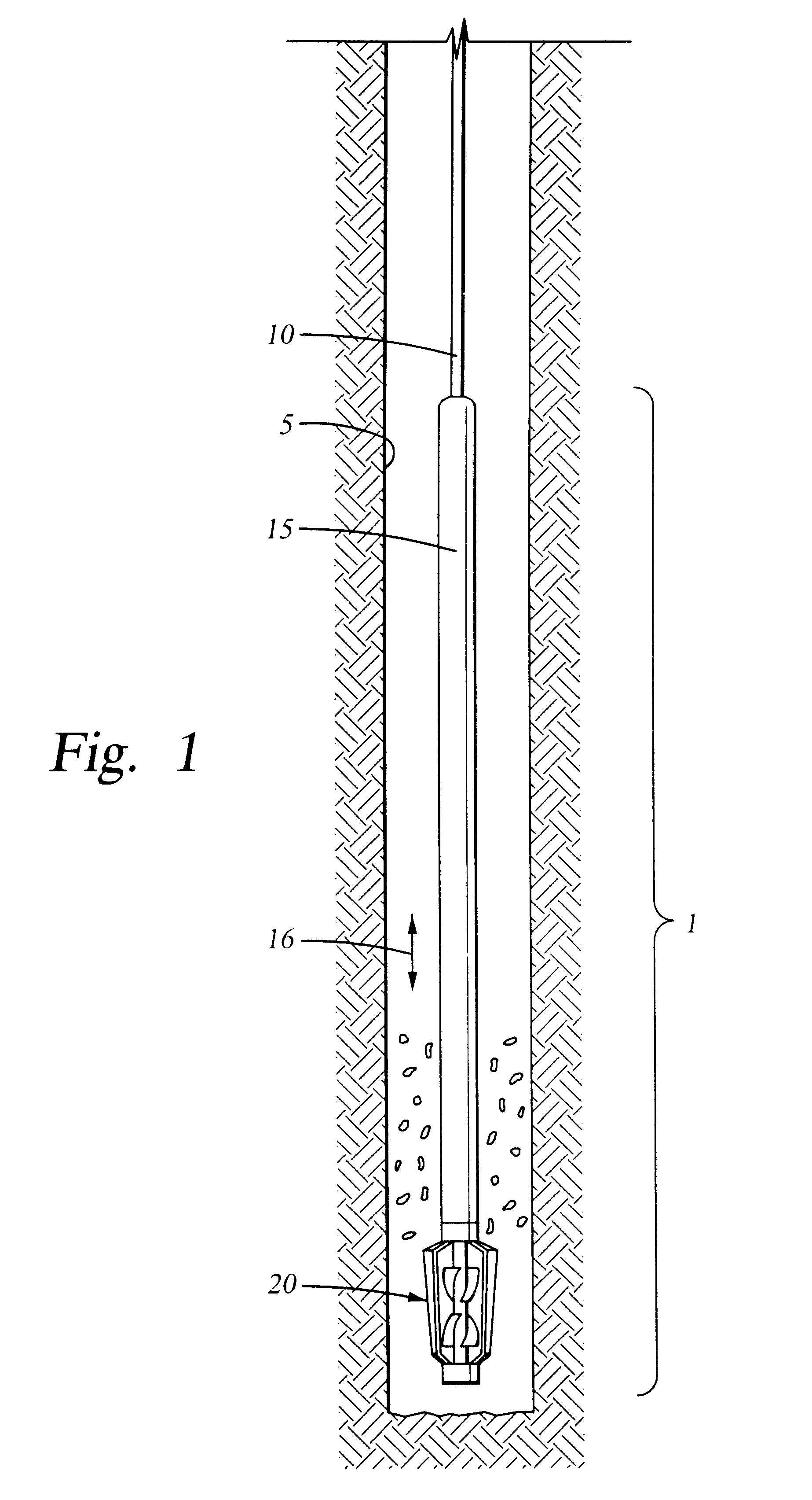
FIG. 1 is a schematic showing of a compensated multiphase flowmeter 1 suspended in a borehole 5 at the end of an electric wireline 10. The wireline 10 runs over pulleys (not shown) at the surface and winds on a surface winch (not shown) allowing the flowmeter 1 to be moved along the borehole 5. The flowmeter 1 is comprised of an electronics module 15 and a sensor module 20 consisting of sensors for characterizing the multi-phase flow in the borehole 5. While the multi-phase flow 16 is typically in the uphole direction, crossflow may occur between different downhole producing layers creating flow in a downhole direction at certain locations. As used herein, multi-phase flow refers to combinations of the physical phases of gas and liquid and to a combination of immiscible fluids such as oil and water, and combinations thereof.

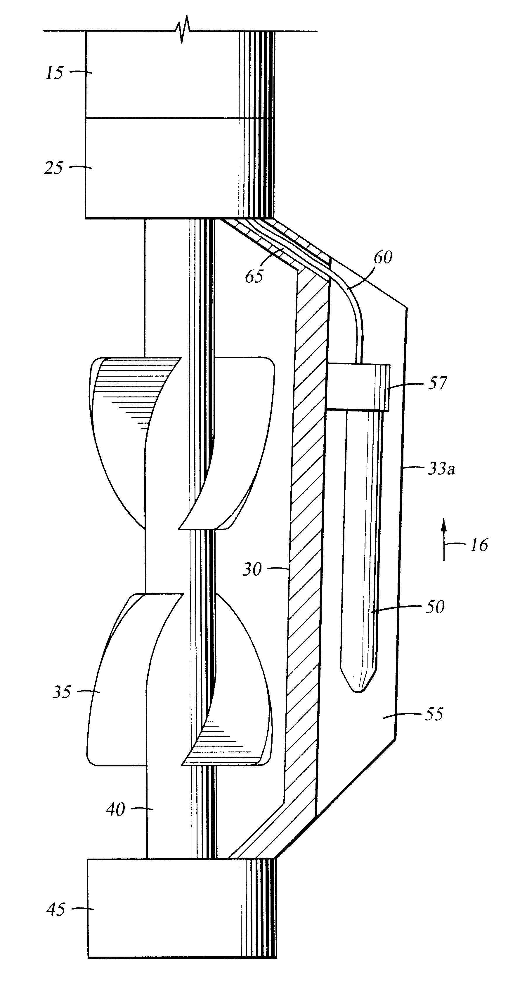
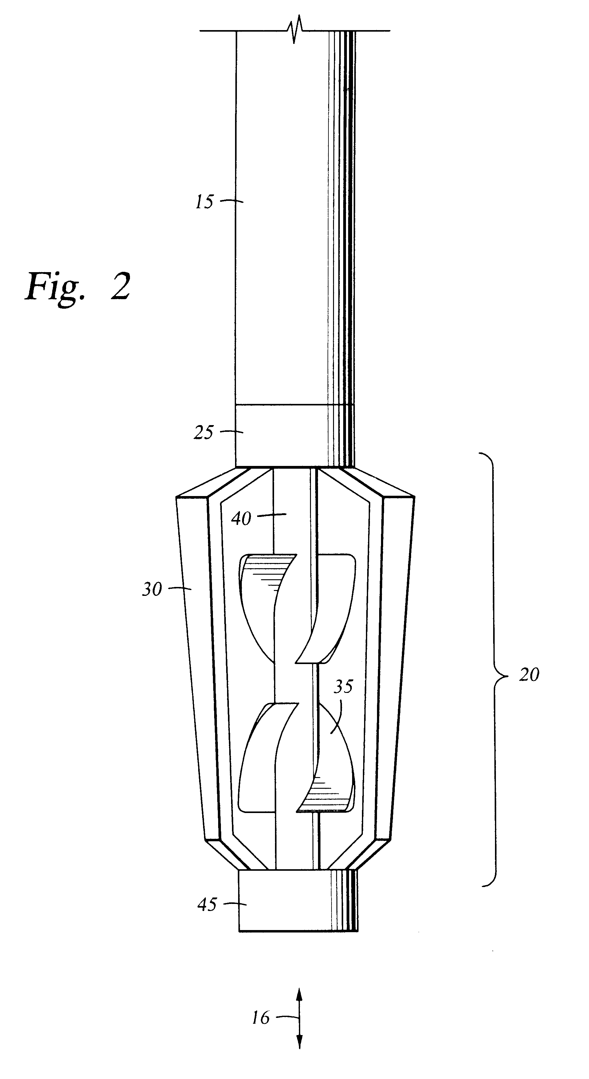
FIG. 2 is a schematic diagram showing the bottom portion of flowmeter 1. Electronics module 15 is connected to sensor module 20. Sensor module 20 comprises an im...


PUM


Abstract

A compensated flow measuring system for measuring a multi-phase fluid flow in a well. An impeller intercepts a downhole multi-phase flow. Capacitance and conductivity sensors are mounted in close proximity to the impeller and provide a measure of electrical admittance of the fluid. In one embodiment, the capacitance and conductivity sensors are mounted in at least one single probe mounted near the impeller. An electronics system contains a phase detector for separating the capacitive and conductive signals and providing a signal related to a compensated multiphase flow rate.

Description

1. Field of the InventionThe present invention relates to the evaluation of formation fluids produced into a wellbore. More particularly, the present invention relates to a system that combines multiple sensors in a single downhole module for compensated multiphase flow evaluation.2. Description of the Related ArtIn petroleum producing wells it is not uncommon to find the well fluid flow regime consisting of multiple phases, such as oil and water, oil and gas, or oil, water and gas. Often, one or more of these phases is an undesired element in the well production flow. For example, in the case of a well fluid flow regime consisting of oil and water, the oil is typically the fluid phase desired to be produced and the water is typically an undesired phase in the production flow. When the degree of water present in the well production flow becomes excessive, logging surveys are run at a plurality of depth locations within the well to facilitate the determining of the flow rates of the ...

Claims


Application Information

Patent Timeline
Patent Type & Authority Patents(United States)
IPC IPC(8): G01F1/10G01F1/05G01F1/74
CPCG01F1/10G01F1/74
Inventor MAXIT, JORGE O.CHACE, DAVIDWANG, JIANRONGGEORGI, DANIEL
Owner BAKER HUGHES INC
Why Eureka
Try Eureka