Differential motion conveyor drive

Inactive Publication Date: 2003-08-05
CARRIER VIBRATING EQUIP
View PDF27 Cites 18 Cited by
  • Summary
  • Abstract
  • Description
  • Claims
  • Application Information

AI Technical Summary

Benefits of technology

With respect to the 3/4" stroke, the conveyor drive with a (0, 0, 0) phase relationship can achieve a conveying speed up to approximately 19 fpm with a much lower operating speed than is required by the conveyor drive with a (0, -90, 180) phase relationship. However, the maximum conveying speed for the conveyor drive with a (0, 0, 0) phase relationship is approximately 19 fpm, whereas the conveyor drive with a (0, -90, 180) phase relationship can achieve a conveying speed as high as 29 fpm.
Similar

Problems solved by technology

For various reasons, it may not be desirable to use the aforementioned vibratory conveyor as the "bouncing" action is not without its disadvantages.
Quite obviously, the movement of the conveyor trough in both horizontal and vertical directions makes it extremely difficult for a worker stationed along the conveyor trough to perform any work on the conveyed material.
Furthermore, the vertical motion of the conveyor trough may cause light particulates to be launched into the air,

Method used


Image

  • Differential motion conveyor drive
  • Differential motion conveyor drive
  • Differential motion conveyor drive

Examples


Embodiment Construction

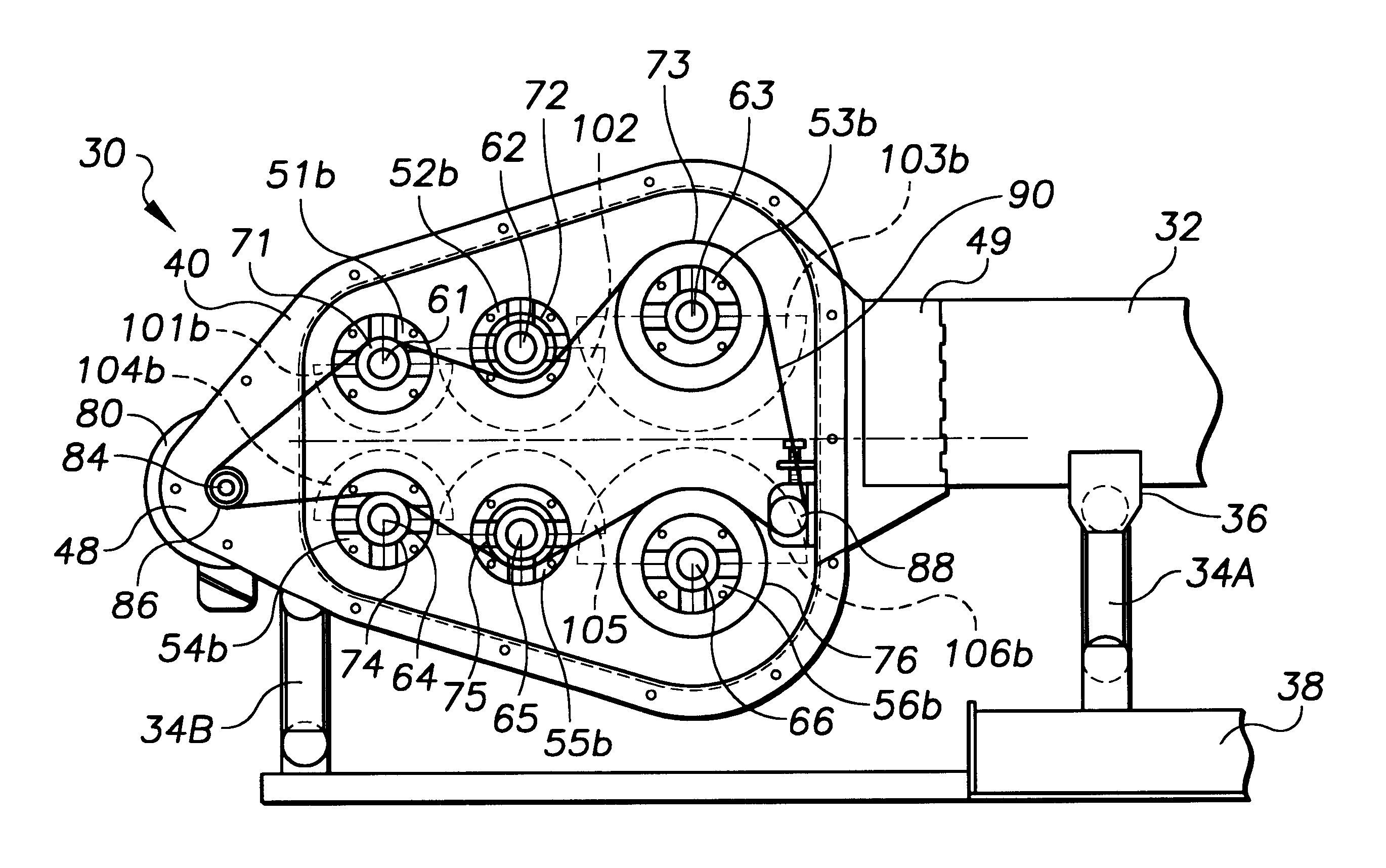
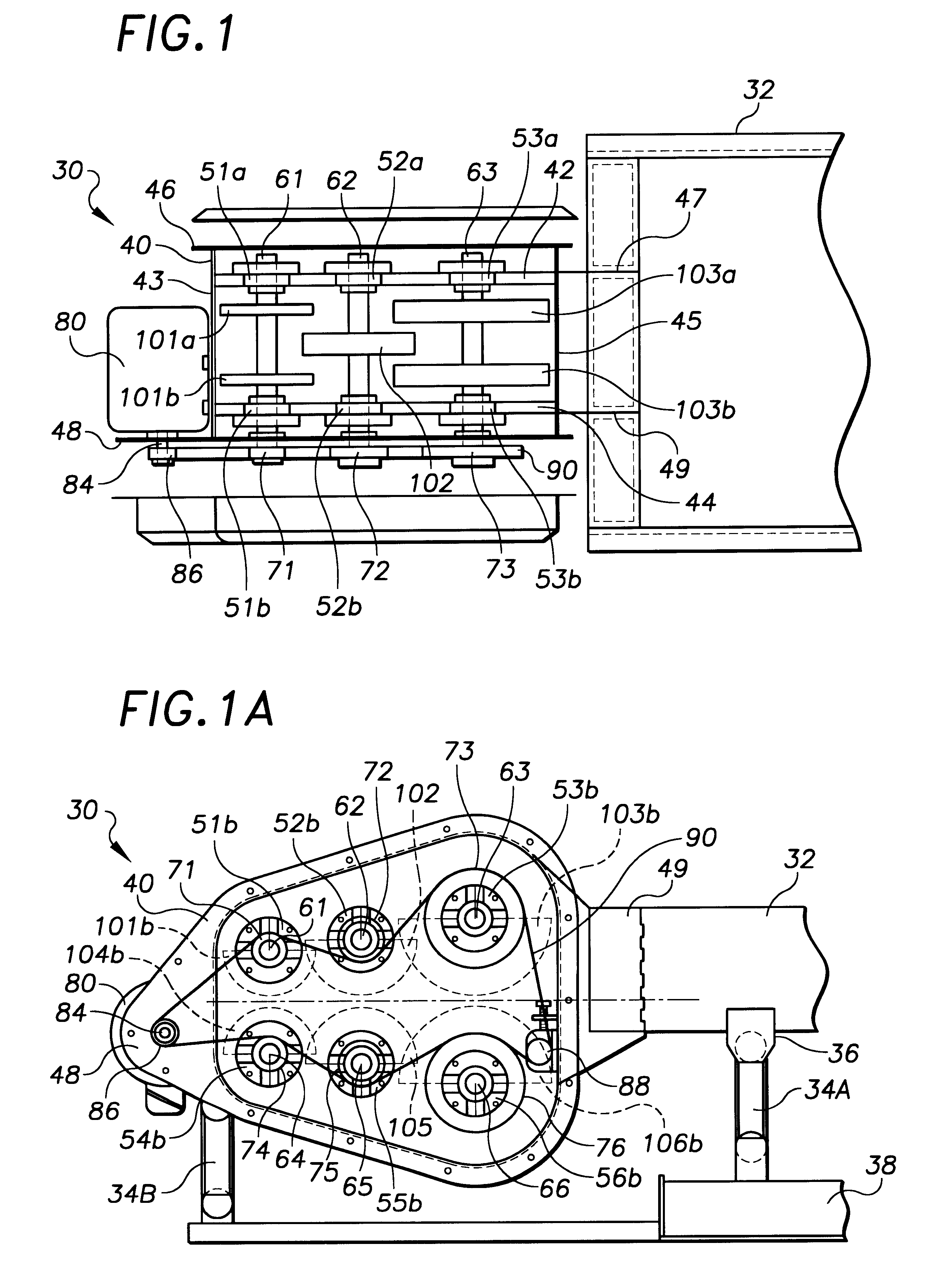
The present invention is a differential motion conveyor drive employing at least six drive shafts carrying eccentric weights that are preferably selected to correspond to the terms of a Fourier series in order to achieve optimal conveying efficiency.

FIGS. 1 and 1A depict a preferred differential motion conveyor drive 30 in accordance with the present invention as secured to an end of a conveyor trough 32. Although only a portion of the conveyor trough 32 is shown in the Figures, the construction of such a conveyor trough 32 is well known in the art. Generally, a conveyor trough 32 is an elongated member which receives material to be conveyed from a delivery conveyor (not shown) at a first or inlet end, and then conveys that material to a second or discharge end where the material to discharged to other processing equipment. Of course, the conveyor trough 32 may be open or closed, and of varying size and dimensions, such factors being largely dependent on the particular material bein...


PUM


Abstract

A differential motion conveyor drive includes at least three pairs of drive shafts carrying eccentric weights that are selected to correspond to the terms of a Fourier series in order to achieve optimal conveying speed and efficiency. To approximate the Fourier series terms, in one preferred embodiment, each of the first pair of shafts carries a weight and rotates at a predetermined operating speed omega. Each of the second pair of shafts carries a smaller weight and rotates at an operating speed 2omega, and each of the third pair of shafts carries an even smaller weight and rotates at an operating speed 3omega. An appropriate weight distribution results in a differential motion conveyor drive that consistently produces a higher conveying speed compared to that produced by a prior art drive throughout a range of operating speeds.

Description

The present invention relates to vibratory conveying equipment for moving bulk material, and, more particularly, to a differential motion conveyor drive.Vibratory conveyors are well known is the art and are commonly used for moving bulk materials. There are two primary types of vibratory conveyors. In a first type, a force is imparted to the material-carrying trough at an angle relative to horizontal plane defined by the trough so that the material moves with the trough along this angle. Once the force is reversed, the trough moves in the reverse direction, allowing the material to fall to the trough in a more forward position. Typically, an eccentric shaft drive system imparts the requisite force to the trough, which is mounted to a stationary support through a plurality of elastic members such as springs. The eccentric shaft drive system comprises one or more rotating shafts and associated drive springs so as to impart the cyclically acting resultant force to the vibratory trough....

Claims


Application Information

Patent Timeline
IPC IPC(8): B06B1/16B06B1/10B65G27/10B65G27/32
CPCB06B1/16B65G27/32
Inventor ROSENSTROM, BO RICHARD
Owner CARRIER VIBRATING EQUIP
Why Eureka
Try Eureka