Method for controlling a light source in a night vision surveillance system

a technology of night vision and surveillance system, applied in the field of night vision surveillance system, can solve the problems of limited application, lll camera may lose its function to observe objects, and each light pulse can only provide a very limited power, so as to improve the observable range of night vision system, reduce light noise, and reduce the effect of nois

Inactive Publication Date: 2003-08-05
NAT CHUNG SHAN INST SCI & TECH
View PDF2 Cites 58 Cited by
  • Summary
  • Abstract
  • Description
  • Claims
  • Application Information

AI Technical Summary

Benefits of technology

It is at least an objective of the present invention to provide a method for controlling a light source in a night vision surveillance system with low light noise. A larger width of the active light pulse is allowed so that the duty cycle is increased and the ON-OFF timing is also properly controlled so that the observable range of the night vision system is improved without conventional issues.
It is at least another objective of the present invention to provide a method for controlling a light source in a night vision system with low light noise. The light noise from the back-scattering light is effectively filtered away so that a higher contrast of observed objects is achieved.
In this manner, the shortest scattering-back distance d.sub.1 is set to be about 0.01 to 0.99 of the observing distance d for a range of about 5 kilometers to get a good observed result according to practical experiences. A little adjustment can be performed to achieve an optimized condition. The back-scattering lights are effectively filtered away so that the contrast of the observed object is increased. A peak power of the pulsed active-light illuminator does not require a high power one. The illuminating performance is also improved.

Problems solved by technology

If the environment is fully dark or light intensity is too low, the LLL camera may lose its function to observe objects.
Since the CW active-light illuminator is affected by the light noise from back-scattering, it is limited to apply in the long-range night vision system.
However, since the light pulse has very short width, each light pulse can only provide a very limited power.
This limits the observing range of the low-light-level camera.
1. For the conventional CW active-light illuminator, the light is continuously emitted. This causes that the low-light-level camera is continuously opened to receive the reflected light from the object. The light noise from the back-scattering light is inevitably received by the camera, causing a deterioration of the performance. In a practical experience, it can only observe the objects within one kilometer or so under a clear night sky.
2. For the conventional PW active-light illuminator, even though the light noise resulting from the back-scattering light can be avoided by proper ON-OFF timing controls, its duty cycle is strongly reduced, causing a need of a light source with very high peak power. Otherwise, the observing range is also limited.
The observing range of the low-light-level camera with above illuminators is limited due to either the light noise or an insufficient peak power of the light source.

Method used


Image

  • Method for controlling a light source in a night vision surveillance system
  • Method for controlling a light source in a night vision surveillance system
  • Method for controlling a light source in a night vision surveillance system

Examples


Embodiment Construction

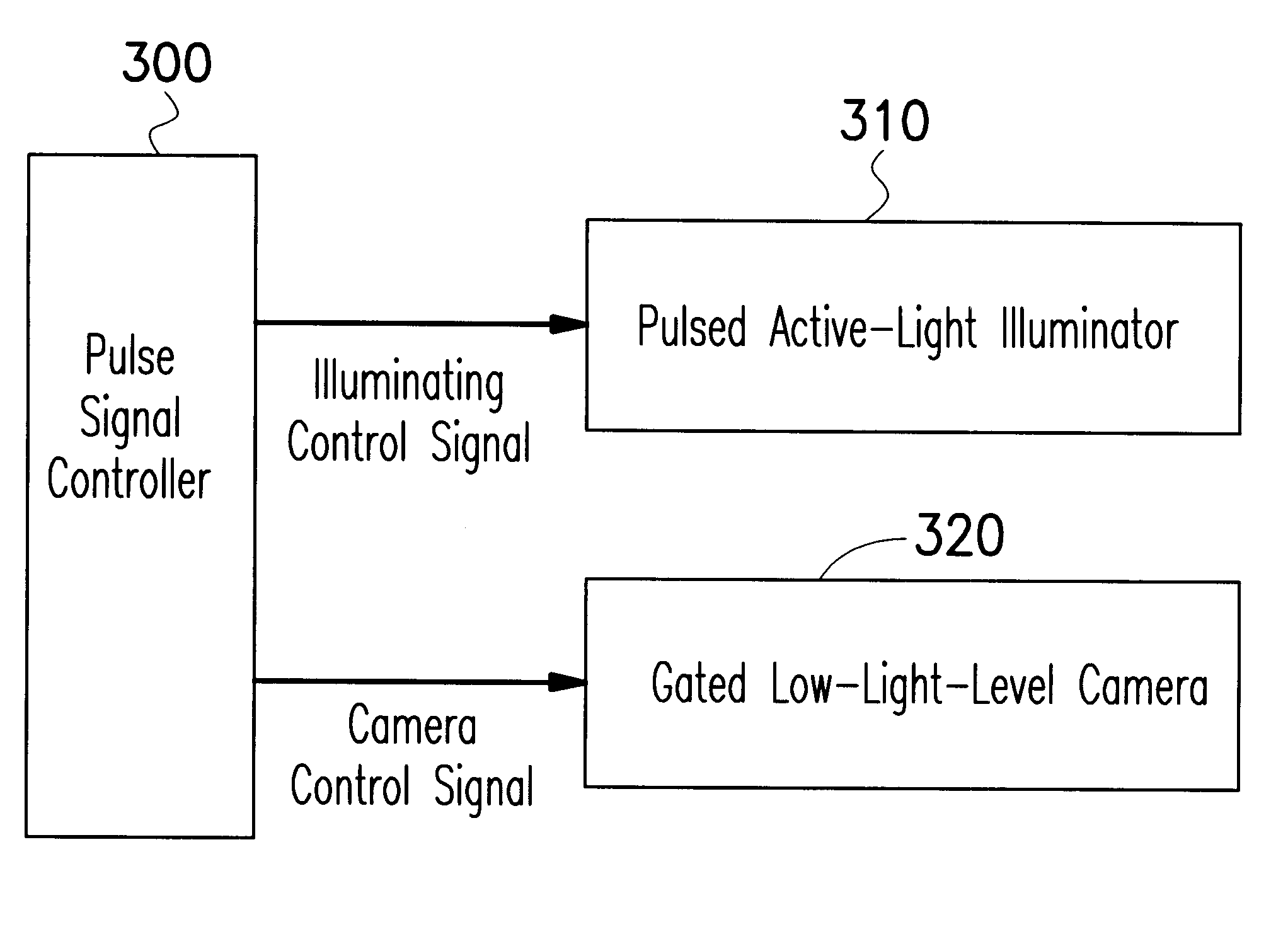
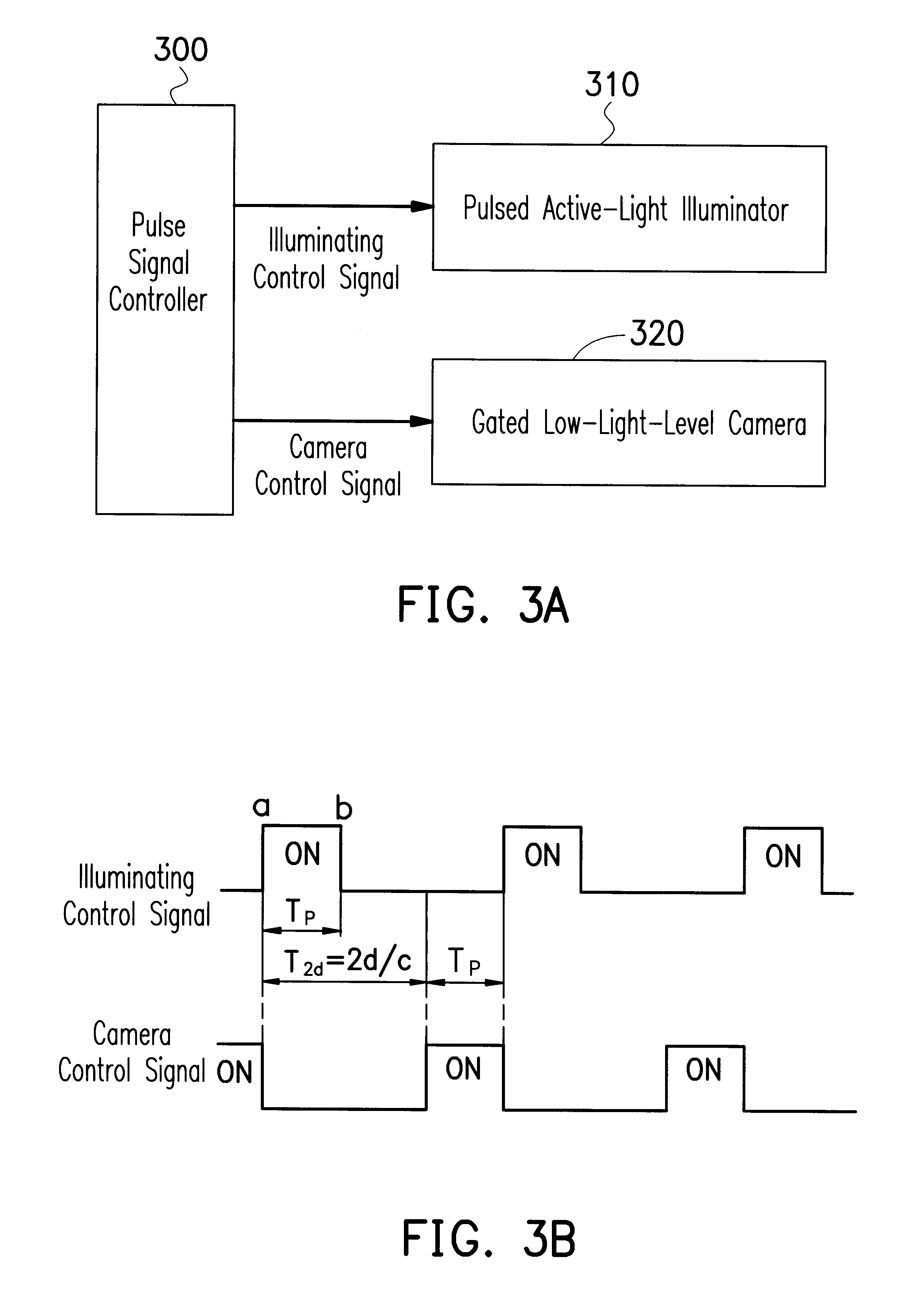
FIG. 3A is a block diagram, schematically illustrating a night vision system with a pulsed active-light illuminator, according to a preferred embodiment of the invention.

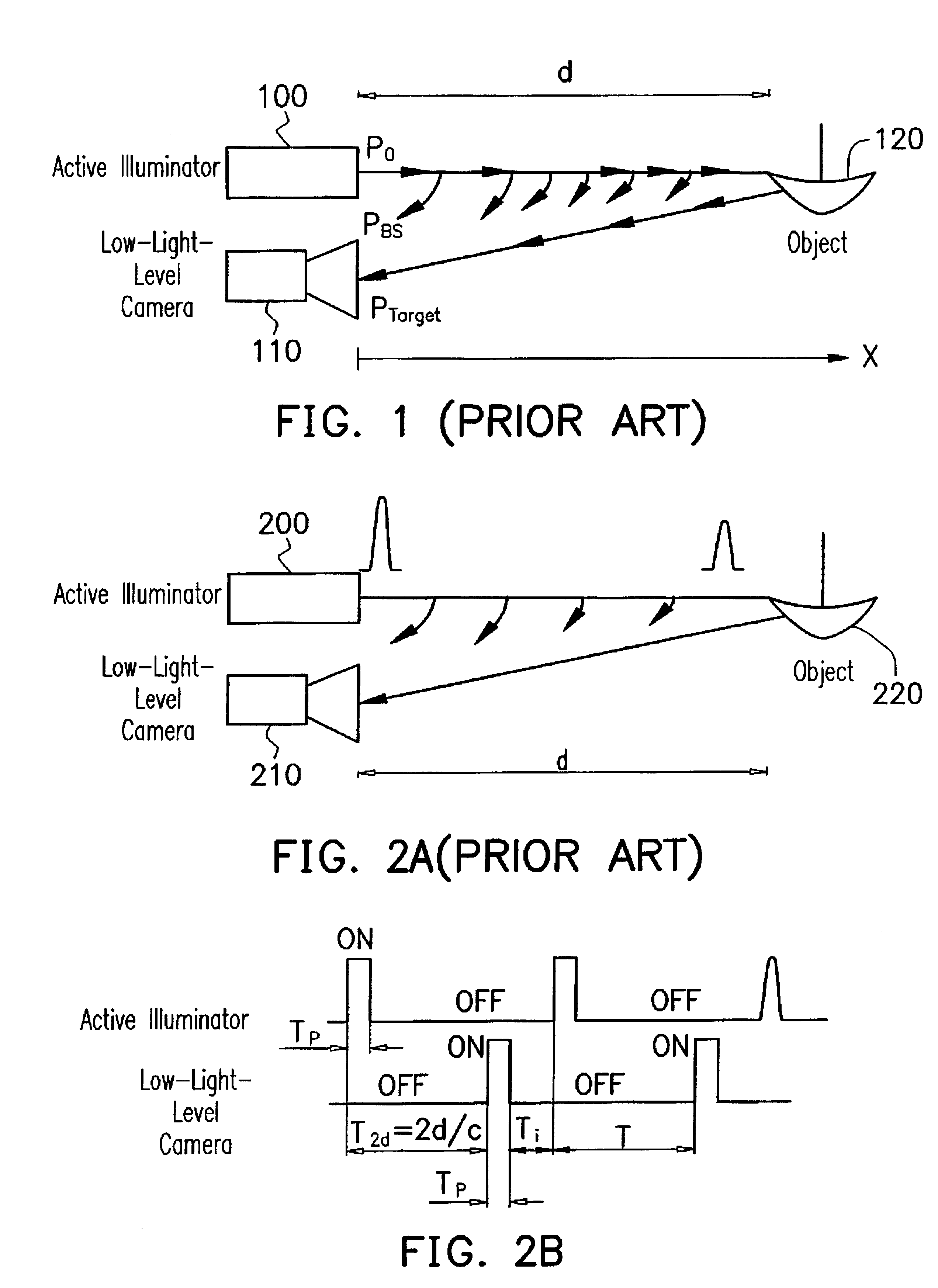
In FIG. 3A, a night vision system includes at least a pulse signal controller 300, a pulsed active-light illuminator 310, and a gated low-light-level camera 320. The pulse signal controller 300 can produce an illuminating control signal to control the pulsed active-light illuminator 310 so as to periodically emit light pulses with a given frequency and a duty cycle D. The pulse signal controller 300 can also produce a camera control signal to control the gated low-light-level camera 320 so as to properly gate it on for receiving the light pulses reflected by an object, which is like the one shown in FIG. 2A.

A consideration about how to improve the performance of the night vision system is following. As a physical phenomenon, a light intensity of the light pulse usually decays when the pulse is reflected by the objec...


PUM


Abstract

A method for controlling a light source in a night vision system is provided. The method first computes a pulse width Tp=2(d-d1) / c, where c is the light speed, according to parameters of a desired observing distance d and a shortest distance d1 of the back-scattering light that enters the light sensor, such as a low-light-level camera. According to the definition of duty cycle D, it is determined by D=(1-d1 / d) / (2-d1 / d). According to the parameters of the desired observing distance and the pulse width, control signals are generated by a pulse signal controller to control a pulsed active-light illuminator with proper emitting period and a gated light sensor with proper gated-on period.

Description

1. Field of the InventionThis invention relates to a night vision surveillance system, and more particularly to a method for controlling a light source in a night vision surveillance system with low light noise.2. Description of Related ArtA low-light-level (LLL) camera, or called as a light intensified camera intensifies its collected light under low light level condition. Under a dim environment with, for example, moon light or star light, the low-light-level camera can collect and intensify the dim light reflected from an object to form a visible image. The LLL camera therefore achieves the purpose to observe objects during the night. Basically, the LLL camera achieves its purpose by intensifying the collected dim light signal. If the environment is fully dark or light intensity is too low, the LLL camera may lose its function to observe objects. In order to solve this problem of insufficient light intensity, a long range night vision surveillance system with high performance usu...

Claims


Application Information

Patent Timeline
Patent Type & Authority Patents(United States)
IPC IPC(8): H04N5/225
CPCH04N5/2256H04N23/56
Inventor JIANG, SHIAW-SHIANGLIN, CHUNN-YENNLIOU, GUANG-HANN
Owner NAT CHUNG SHAN INST SCI & TECH
Why Eureka
Try Eureka