Crop processor and blower arrangement for a forage harvester

Inactive Publication Date: 2003-08-12
BLUE LEAF I P +1
View PDF5 Cites 32 Cited by
  • Summary
  • Abstract
  • Description
  • Claims
  • Application Information

AI Technical Summary

Benefits of technology

Preferably, the distance from the output of the cutter unit to the input of the crop processor unit in the first position is about the same as the distance from the output of the cutter unit to the input of the blower unit when the crop processor unit is in the second position. When this is the case there is a reduced chance that comminuted crop material from the cutter units blocks or jams in the chute or duct leading to the blower unit when the crop processor unit is bypassed. Preferably, the blower unit and the crop processor unit are mounted in a frame such that rotation of this frame between the first and second positions is permitted without the removal or disassembly of any drive component of the processing unit, e.g. removal or changing of belt drives or gears. In accordance with one embodiment the crop processor rolls are raised from a low non-crop engaging position to a higher crop engaging position. In the lower position a guide plate may be positioned to isolate the crop processor unit from the blower unit and / or the duct leading to the blower unit.

Problems solved by technology

This reduces the nutrient value of the silage crop as the kernels are more-or-less indigestible if not cracked.
When chopping other kernel-free crops such as grass or alfalfa, the crop processor is redundant but the rolls may still be worn by the sand / earth in the crop material and damaged by stones therein.
In a number of conditions, especially with light or sticky crops, this can result in poor crop transport from cutterhead to the blower or accelerator due to lack of kinetic energy of the material, causing blockage of the channel between cutterhead and blower or accelerator.
All these known solutions have the problem in common that when the crop processor is removed or in an inactive condition the distance from the cutterhead to the blower or crop accelerator is large.
Under adverse conditions the long duct between the cutterhead and the blower can become blocked.
This increases the cost and power consumption of the harvester.
This means the changeover cannot be carried out from the drive cab.
Also it is difficult to prevent some crop material from accumulating in the crop processor when it is in the inactive position.

Method used


Image

  • Crop processor and blower arrangement for a forage harvester
  • Crop processor and blower arrangement for a forage harvester
  • Crop processor and blower arrangement for a forage harvester

Examples


Embodiment Construction

The present invention will be described with reference to certain embodiments and certain drawings but the invention is not limited thereto but only by the claims. The drawings are schematic. The terms "front", "rear", "forward", "rearward", "right" and "left" used throughout the specification are determined with respect to the normal direction of movement of the machine in operation and are not to be construed as limiting terms.

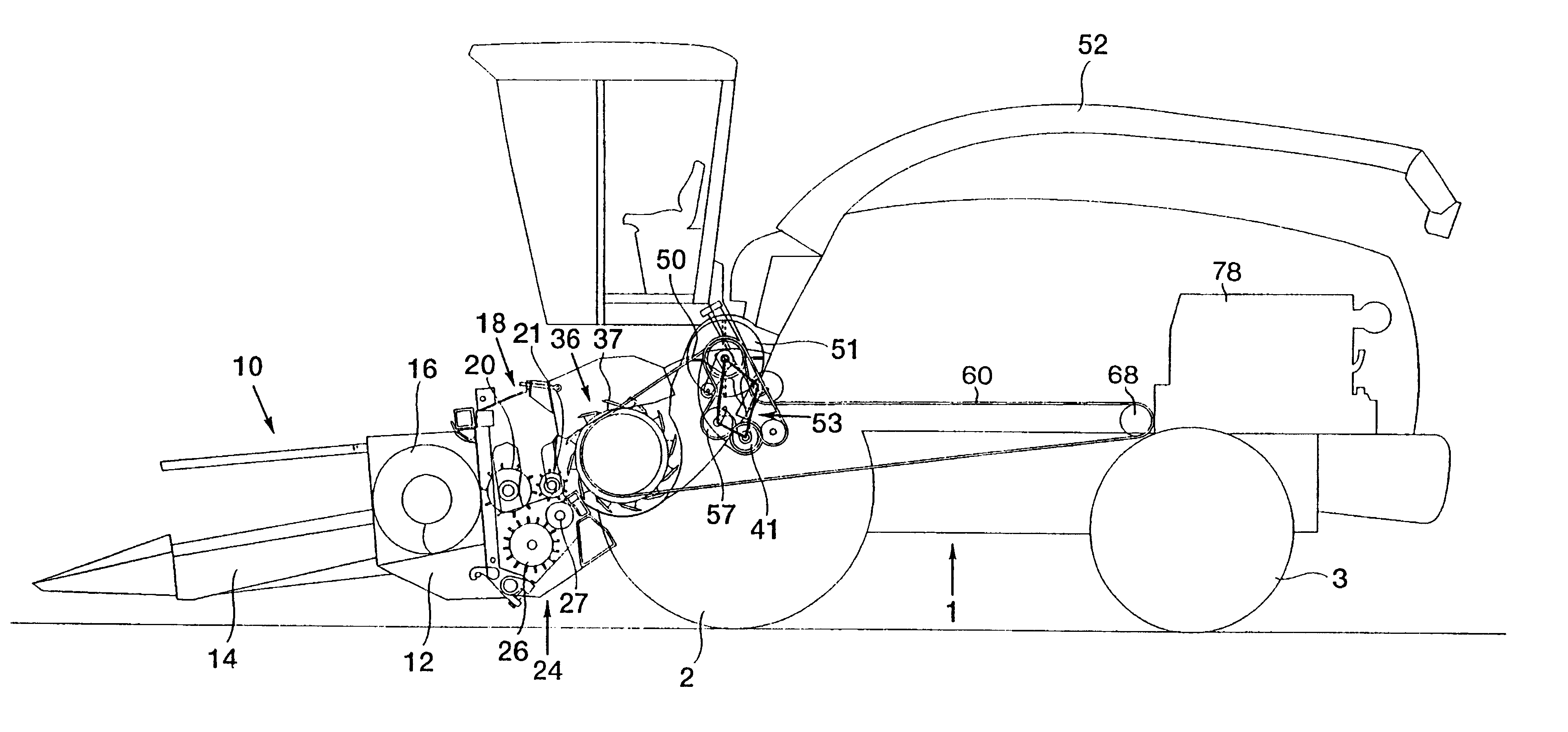
With reference to the drawings and more particularly to FIG. 1, there is shown a forage harvester having a main frame 1 on which are mounted ground engaging traction wheels 2 and steering wheels 3. The forage harvester is shown equipped with a crop collecting apparatus, in the form of a row crop attachment 10, suitable for the harvesting of maize, but which can be replaced with a conventional windrow pick-up device or a conventional cutter bar attachment, depending on the type of crop to be harvested. Customarily, the row crop attachment 10 comprises an atta...


PUM


Abstract

A forage harvester having a crop processor unit, a cutter unit operable to comminute crop material and a processor unit movably disposed between first and second positions. In the first position, the processing unit receives comminuted crop material from the cutter unit. In the second position, comminuted crop material from the cutter unit bypasses the crop processor unit. A blower unit is disposed to move with the crop processor between the first and second positions, the blower unit receiving the processed crop material directly form the crop processor unit when in the first position and directly from the cutter unit when in the second position, in both cases accelerating the processed crop material towards a handling apparatus.

Description

The present invention relates generally to forage harvesters having means for processing crop material including maize kernels, these means, for instance, comprising a compressor roll assembly, operable to crack the maize kernels as well as means for processing kernel-free crops such as alfalfa or grass.TECHNICAL BACKGROUNDA forage harvester is an agricultural machine for comminuting crop material for silage purposes. A harvester is mainly used to harvest grass and maize. With grass-like materials (kernel-free) it is sufficient to slit the crop material, e.g. the stems of the plants are cut to length using a cutter, e.g. a rotating knife drum. When cutting maize the cobs may be slit into smaller size but the majority of the kernels are not broken or cracked. This reduces the nutrient value of the silage crop as the kernels are more-or-less indigestible if not cracked. A cutterhead unit of a forage harvester is used to receive crop material harvested from the field and comminute it i...

Claims


Application Information

Patent Timeline
IPC IPC(8): A01D43/08A01D43/00A01F29/09
CPCA01D43/086A01D43/10A01D69/00
Inventor TYVAERT, PAUL C.DESNIJDER, DIRK J.
Owner BLUE LEAF I P
Why Eureka
Try Eureka