
Apparatus and method for measuring the maximum speed of a runner over a prescribed distance

a technology of a runner and a device, applied in the field of pedometers, can solve the problems of no prior art device designed to measure the maximum speed of a runner over a prescribed distance, difficult to continue walking or running for a long period of time, and no way of knowing whether the runner is running or no

Inactive Publication Date: 2003-08-12
BBC INT
View PDF6 Cites 59 Cited by
  • Summary
  • Abstract
  • Description
  • Claims
  • Application Information

AI Technical Summary

Problems solved by technology

Although much has been done in this field to introduce distance measurements and pace monitoring to footwear, none of these prior art devices is designed to measure the maximum speed achieved by a runner over a prescribed distance in order to motivate the wearer of the device to run as fast as possible.
It is difficult to continue walking or running for a long period of time.
Further, without knowing how fast they have run, a runner will have no way of knowing whether they are making progress toward maximizing their speed during an exercise session.
Moreover, a runner can grow tired of walking or running without any external encouragement.

Method used


Image

  • Apparatus and method for measuring the maximum speed of a runner over a prescribed distance
  • Apparatus and method for measuring the maximum speed of a runner over a prescribed distance
  • Apparatus and method for measuring the maximum speed of a runner over a prescribed distance

Examples


Embodiment Construction

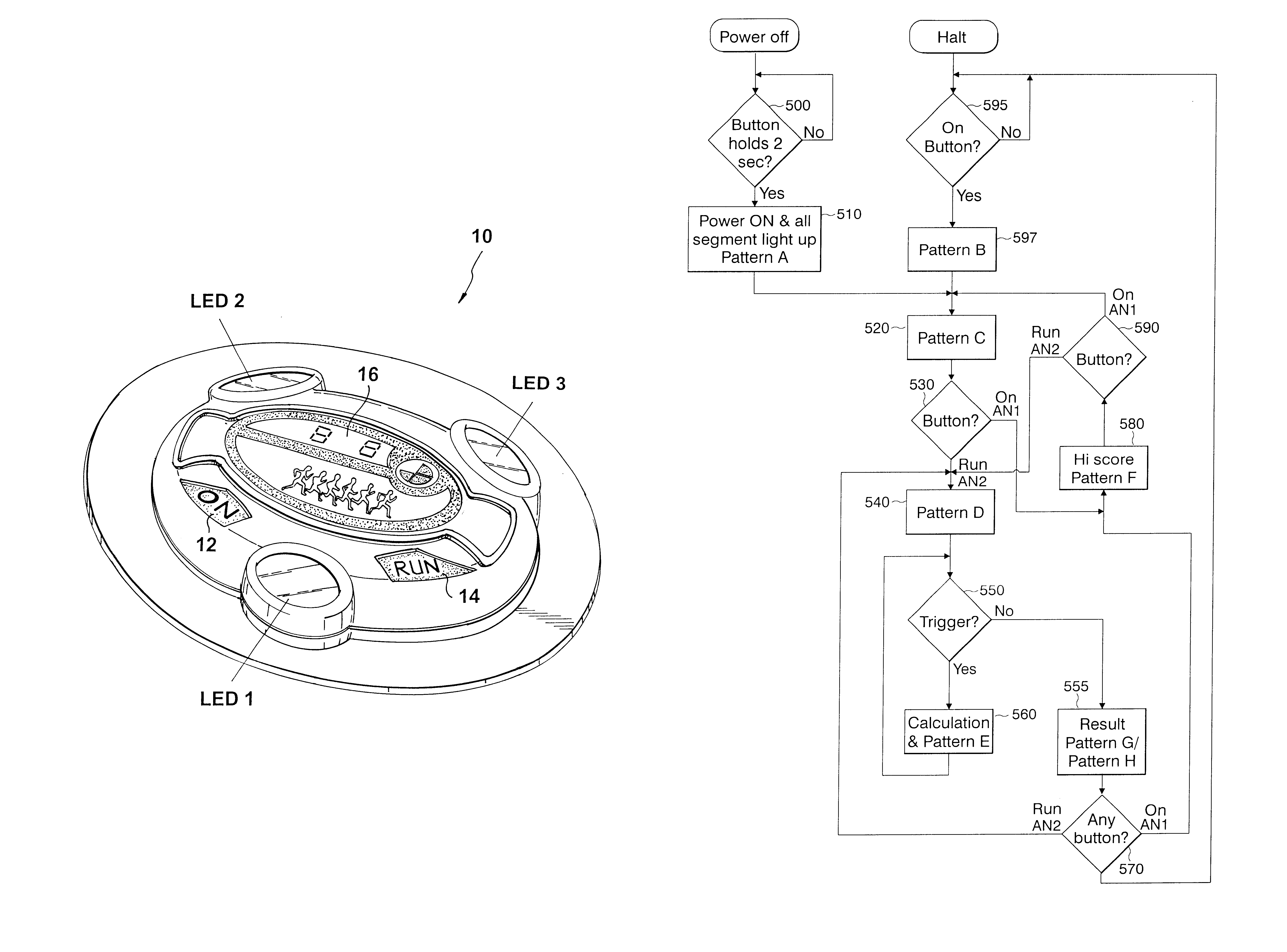
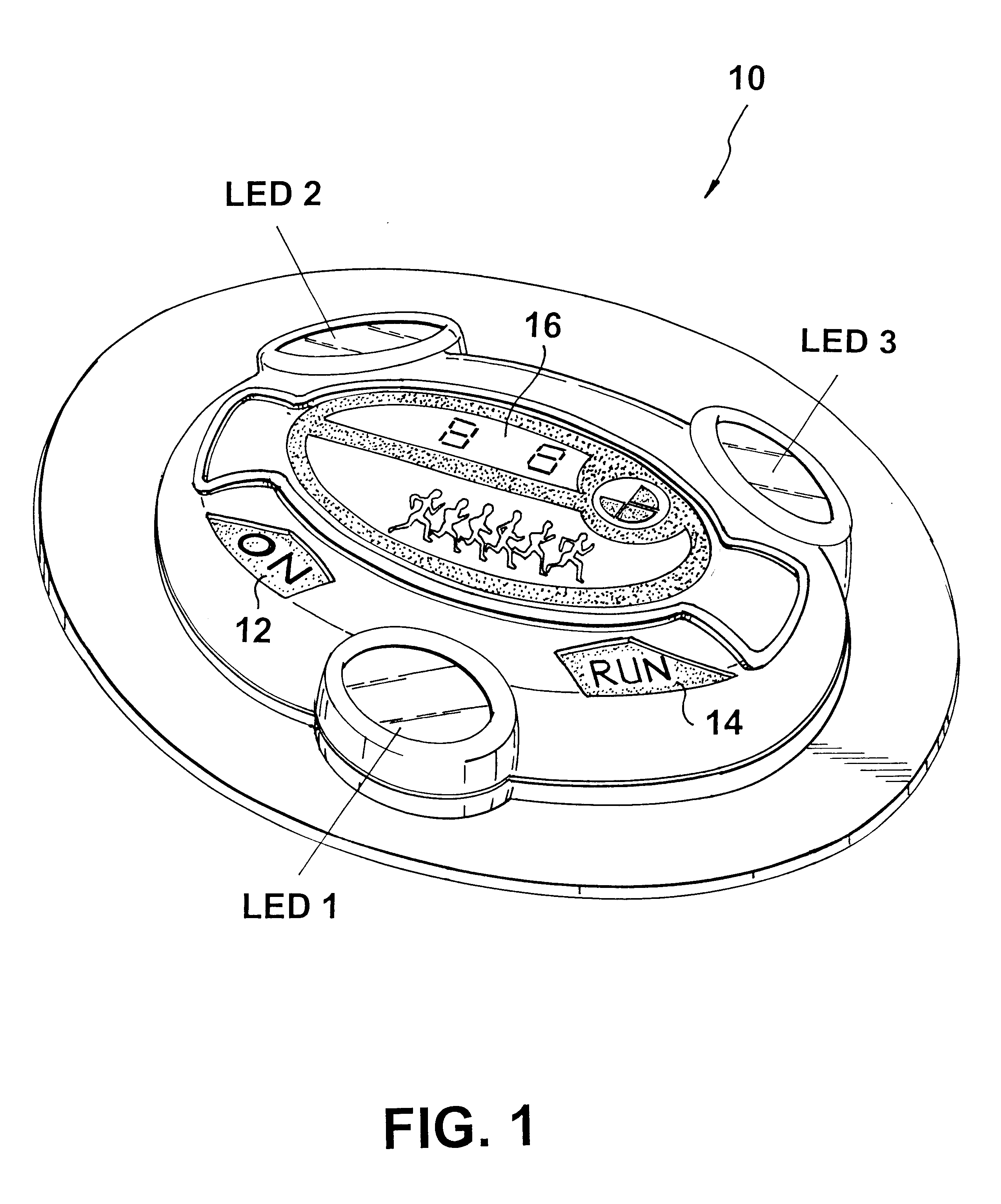
FIG. 1 is an illustration of a control panel for the device 10 in accordance with a preferred embodiment of the invention. The console of the device 10 comprises push buttons 12 and 14 for activating and deactivating the device, respectively. Also included are LED 1, LED2 and LED3, which are used to display the status of the device and to flash in response to movement of a user wearing the device while running or walking. The console of the device 10 also includes a liquid crystal display (LCD) 16 which displays various messages to the user, such as the last recorded speed achieved, the highest speed achieved and the average miles per hour achieved, respectively.

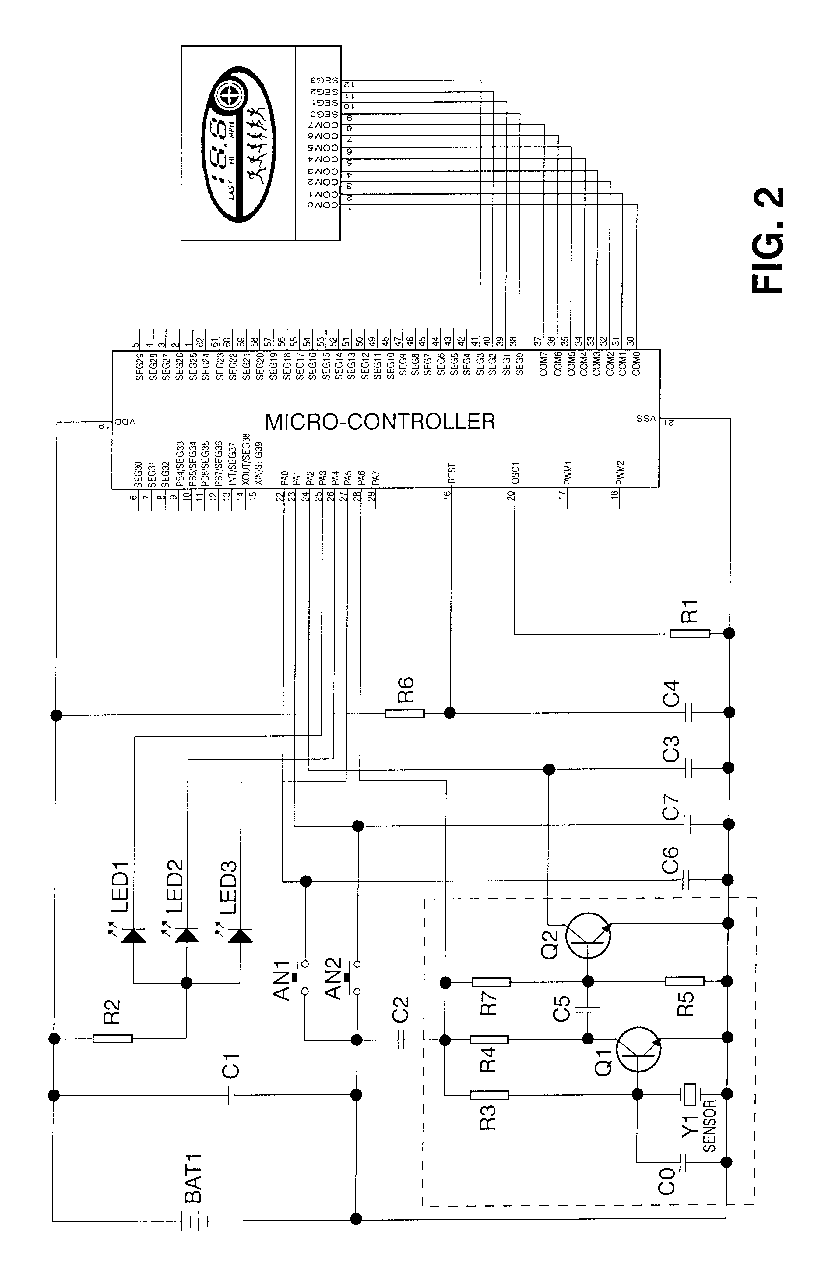
FIG. 2 is an illustration of an exemplary circuit for calculating, presenting, recalling and recording a speed of a user over a prescribed distance. The principal element of the circuit is a micro-controller 20, which is capable of making calculations based on various inputs according to a stored program and is further capab...


PUM


Abstract

A method and apparatus for calculating, presenting, recalling and recording the maximum running speed of a user over a prescribed distance in miles per hour or meters per second. The result is shown in digital and iconic form on a liquid crystal display (LCD). The apparatus incorporates a micro-controller, a LCD, a motion sensor, a sound generator, press switches, and light emitting diodes. The motion sensor is used to generate a signal, in response to external motion, which is input to the micro-controller for use in calculating the speed in accordance with a prescribed formula. Upon completion of running over a fixed time period or distance, a message is displayed on the LCD to indicated the maximum speed achieved by the user during an interval of the fixed time and over the prescribed distance. The apparatus may be adapted for use on shoes, a user's wrists, or the like, for the purpose of encouraging the user to run as fast as possible, and to ensure safety of the user at night.

Description

1. Field of the InventionThe present invention generally relates to pedometers and, more particularly, to an apparatus and method for measuring the maximum speed of a runner over a prescribed distance.2. Description of the Related ArtToday, it is not uncommon for shoes to include entertaining and functional electronics. The electronics usually include a simple timing circuit and / or a movement-sensitive switch, a battery, and an array of LED-type lights. The electronic circuit of the type typically found in popular shoes today is used to illuminate the LEDs either at regular (or predetermined) intervals, or whenever the shoes are moved a predetermined degree, such as when the wearer walks, jumps, or runs. It appears that the primary purpose of the lighting circuit located in today's shoes is to entertain both the wearer of the shoes, and those in the vicinity. It also appears that the timing circuit and / or the movement-sensitive switch are experiencing increased use in determining th...

Claims


Application Information

Patent Timeline
Patent Type & Authority Patents(United States)
IPC IPC(8): A43B3/00A63B24/00A63B69/00G01C22/00
CPCA43B1/0036A63B24/00A63B69/0028G01C22/006Y10S482/901
Inventor GUZMAN, RUDY
Owner BBC INT
Learn More