Automotive air conditioning system

a technology for air conditioning systems and automobiles, which is applied in the field of air conditioning systems, can solve the problems that the air conditioning systems of the above-mentioned dual type have failed to give users satisfaction, and the second air conditioning unit of the system has failed to provide the rear part of the passenger room with a satisfactorily warm air

Inactive Publication Date: 2003-08-12
CALSONIC KANSEI CORP
View PDF60 Cites 57 Cited by
  • Summary
  • Abstract
  • Description
  • Claims
  • Application Information

AI Technical Summary

Problems solved by technology

However, due to inherent construction, the air conditioning systems of the above-mentioned dual type have failed to give users satisfaction.
That is, the second air conditioning unit of the systems has failed to provide the rear part of the passenger room with a satisfactorily warmed air particularly in cold seasons.

Method used


Image

  • Automotive air conditioning system
  • Automotive air conditioning system
  • Automotive air conditioning system

Examples


first embodiment

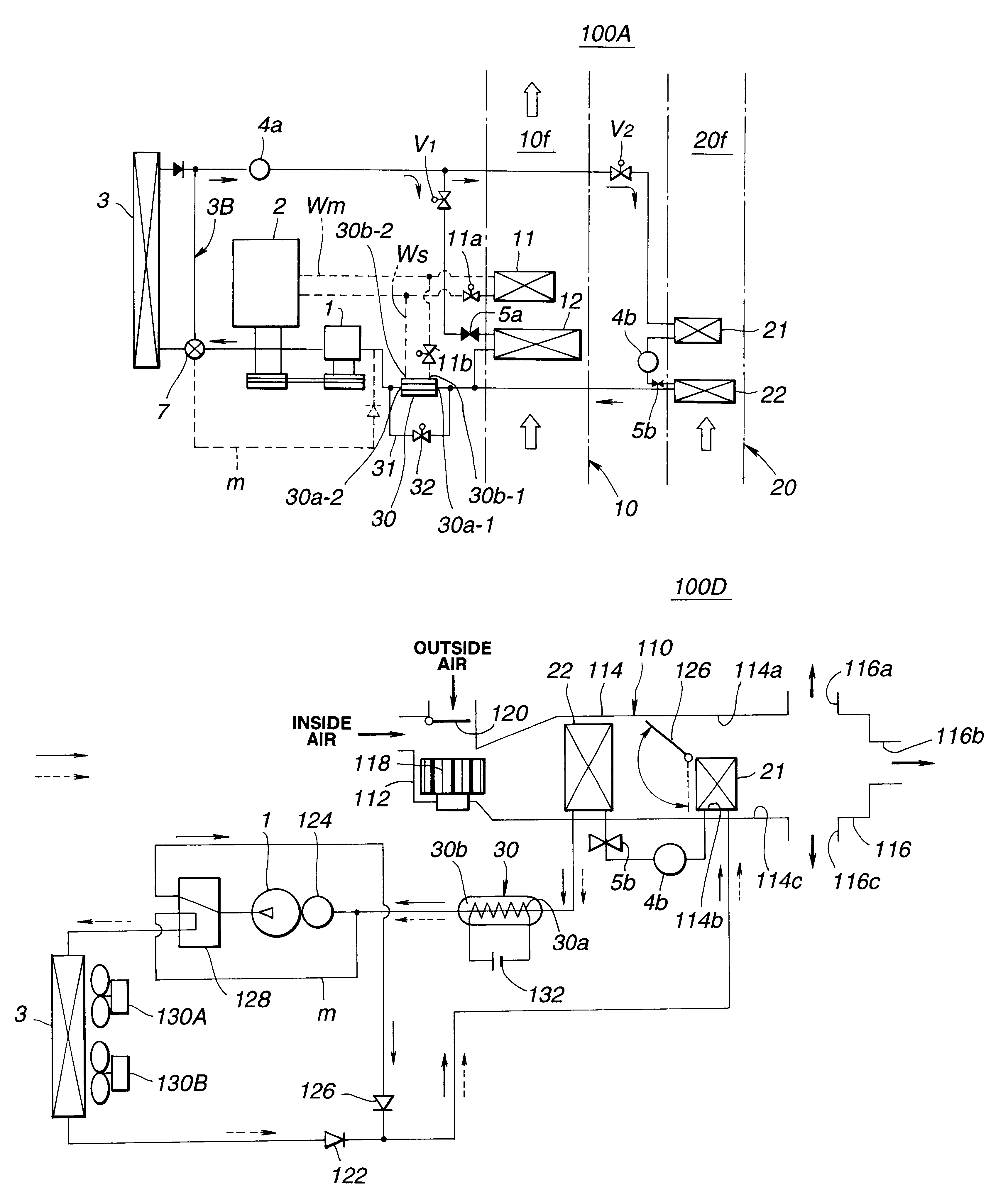
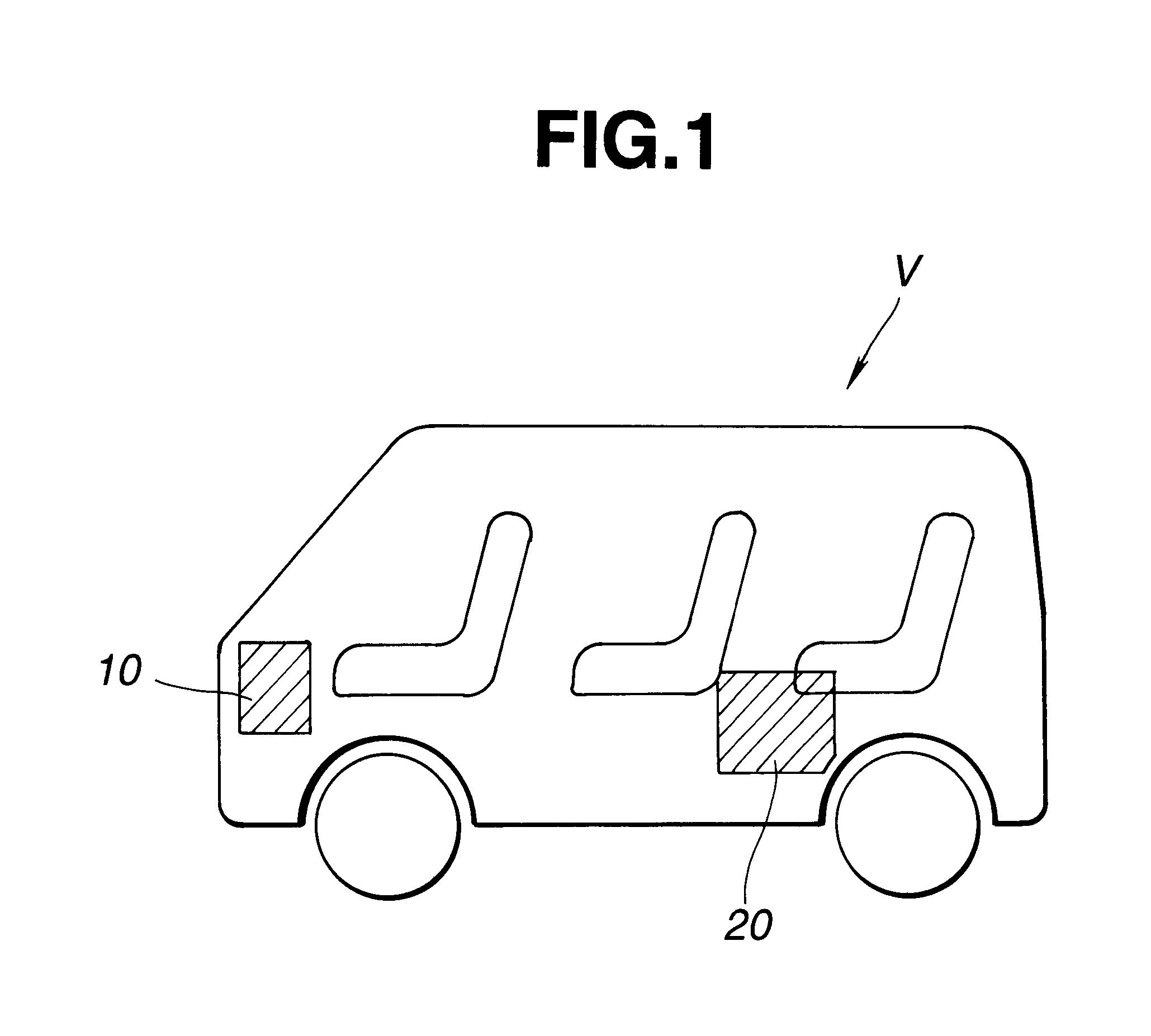
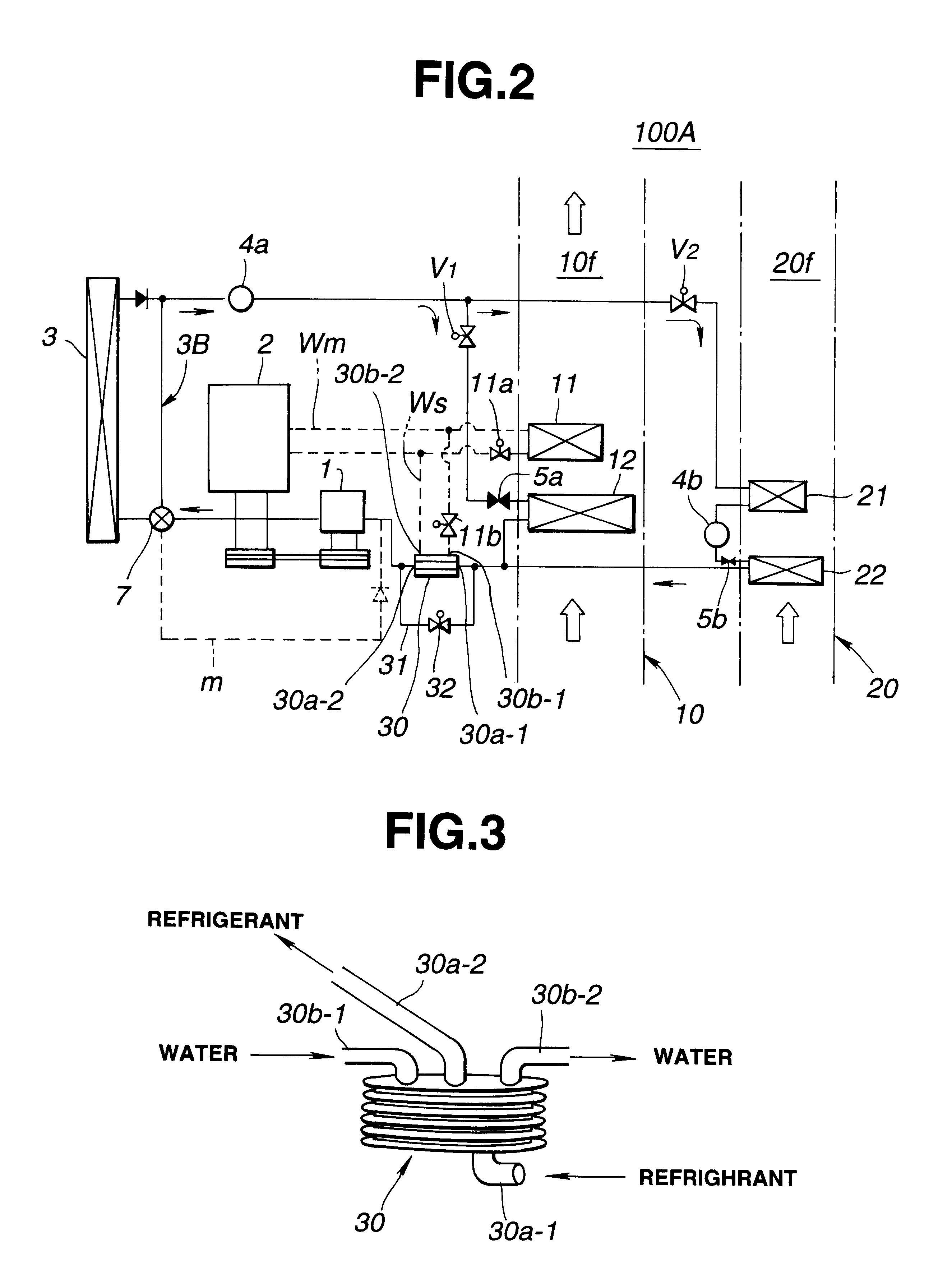
Referring to FIGS. 1 to 3, there is shown an automotive dual air conditioning system of the present invention, which is generally designated by numeral 100A.

As is seen from FIG. 1, the dual air conditioning system 100A generally comprises a first air conditioning unit 10 mounted on a relatively front portion of a vehicle "V", a second air conditioning unit 20 mounted on a relatively rear portion of the vehicle "V" and interconnecting means which operatively connects is the first and second systems 10 and 20 in such a manner as will be described hereinafter. As is understood from the drawing, the first and second air conditioning units 10 and 20 are arranged and constructed to condition air blown into relatively front and rear portions of a passenger room, respectively. That is, the first unit 10 selectively takes outside air (viz., air outside the vehicle) and / or inside air (viz., air in the passenger room) and conditions the air before discharging the same to the front portion of t...

second embodiment

Referring to FIG. 4, there is shown an automotive dual air conditioning system 100B which is the present invention.

Since the system 100B of this second embodiment is similar to the above-mentioned system 100A of the first embodiment, only portions and parts which are different from those of the first embodiment will be described in detail in the following. Substantially same portions and parts as those of the first embodiment 100A are denoted by the same numerals.

As is seen from FIG. 4, in this second embodiment 100B, there are no means which correspond to the bypass circuit 31 and the valve 32 which are used in the first embodiment 100A. Furthermore, the extra heat exchanger 30 is arranged in a refrigerant line just downstream of the second heat exchanger 22. As shown, a refrigerant line from the output of the extra heat exchanger 30 to connected to a refrigerant line which extends from an output of the first heat exchanger 12 to the compressor 1.

As is well shown in FIG. 4, in this...

third embodiment

Referring to FIG. 6, there is shown an automotive dual air conditioning system 100C which is the present invention.

Since the system 100C of this third embodiment is similar to the above-mentioned system 100B of the second embodiment, only portions and parts which are different from those of the second embodiment will be described in detail in the following. Substantially same portions and parts as those of the second embodiment 100B are denoted by the same numerals.

As is seen from FIG. 6, in this third embodiment 100C, there is no means corresponding to the second heat exchanger 22 used in the second embodiment 100B. That is, the outlet of the second condenser 21 is connected to the inlet line 30a-1 of the extra heat exchanger 30 through the liquid tank 4b and the second expansion valve 5b. Further, there is no means corresponding to the added measure (including the temperature sensor 40 by which the second expansion valve 5b is controlled) employed in the second embodiment 100B.

Fur...


PUM


Abstract

An air conditioning system for a vehicle has a first cycle including a compressor, a first condenser, a second condenser, a liquid tank, an expansion valve and an evaporator which are connected through pipes to form a first refrigerant circulation circuit through which a refrigerant flows from an outlet of the compressor to an inlet of the compressor while changing the phase. The first cycle causes the evaporator to act as a cooler when operated. The system further has a second cycle including the compressor, the second condenser, the liquid tank, the evaporator and the evaporator which are connected through pipes to form a second refrigerant circulation circuit through which the refrigerant flows from the outlet of the compressor to the inlet of the compressor while changing the phase. The second cycle causes the condenser to act as a heater and the evaporator to act as a cooler when operated. The first and second cycles are switched by switch means. The system further has an air duct case having an air flow passage in which the second condenser and the evaporator are installed. The air flow passage is connected at its downstream part to a passenger room of the vehicle. The air conditioning system further comprises heater means for heating a returning refrigerant which, under operation of the second cycle, flows in the pipe extending from an outlet of the evaporator to the inlet of the compressor.

Description

1. Field of the InventionThe present invention relates in general to air conditioning systems of a motor vehicle, and more particularly to automotive air conditioning systems of a double function type which has two function cycles, one being a cycle for cooling air by practically using the system as a closed refrigeration system and the other being a cycle for heating air while dehumidifying the same by practically using the system as a heat pump system.2. Description of the Prior ArtHitherto, various types of air conditioning systems have been proposed and put into practical use particularly in the field of motor vehicles. Some are of the above-mentioned double function type.In long body passenger cars, such as one-box type vehicle or the like, there have been also used a so-called duel air conditioning system which comprises a first air conditioning unit for conditioning air in a relatively front part of a passenger room and a second air conditioning unit for conditioning air in a...

Claims


Application Information

Patent Timeline
Patent Type & Authority Patents(United States)
IPC IPC(8): B60H1/00B60H1/32F28D1/04F28D7/10
CPCB60H1/00878B60H1/323B60H1/00342F28D7/106F28D1/0408
Inventor NODA, YOSHITOSHIYAMAGUCHI, HIROYUKITAJIMA, TADAYOSHIYOSHIOKA, HIROKIOHASHI, TOSHIOABE, KENICHI
Owner CALSONIC KANSEI CORP
Why Eureka
Try Eureka