Top for a convertible vehicle

a convertible vehicle and top technology, applied in the direction of windows, windscreens, roofs, etc., can solve the problems of not being able to pivot the deposited top up in the direction of travel together with the second element, and only achieve the movement of the rigid rear window through a linear driv

Inactive Publication Date: 2003-08-12
WEBASTO EDSCHA CABRIO
View PDF21 Cites 68 Cited by
  • Summary
  • Abstract
  • Description
  • Claims
  • Application Information

AI Technical Summary

Benefits of technology

It is particularly advantageous if the rear element is fixed on the frame element by means of a four-bar linkage, thus allowing a sequence of motion of the rear element which allows optimum and joint-free fitting of the rear element into the remainder of the vehicle body in the closed state. During an opening process of the rear element, the sequence of motion made possible by a four-bar linkage, corresponding to the superimposition of a rotary motion and a translatory motion, provides a simple means of avoiding collision with non-moving parts of the vehicle body.
In a preferred embodiment of the invention, the main bearing is fixed on the frame element in the vicinity of the axis of the frame element, the said axis being fixed relative to the body, with the result that, as the frame element is pivoted up, the roof part, which is deposited in the open state, is pivoted together with the frame element without the need for a complex mechanism for coupling the axes of the top and the frame element.
In a preferred refinement of the invention, the roof part comprises a rigid rear window, which is pivoted with respect to the roof part in the open, deposited position of the roof part, the pivoted rear window thus making available a particularly large useable luggage-space volume. It is advantageously possible here for a further roof segment to be provided, which is likewise pivoted out of the area of the roof part in the open, deposited position, with the result that the roof part now has a U-shaped opening, the two legs of the U corresponding to the C pillars of the vehicle, a free through-loading space being created in the folded-over deposited position of the roof part by virtue of the fact that the U-shaped roof part is deposited with the opening of the U pointing downwards and rearwards.
It is particularly advantageous if a central roof part and a front roof part are provided in addition to the roof part, the roof part, the central roof part and the front roof part being connected to one another by means of a linkage, which forms a positive control means, a three-part hard-shell folding top thereby being formed overall. To control this three-part hard-shell folding top, main links connected pivotally to the main bearing at a distance apart can then be provided, and these, for their part, can be driven by means of a driving device comprising a hydraulic cylinder and a link mechanism. Overall, this provides a convertible top with three shell elements, a pivotable rear window and a roof segment, which, on the one hand, is suitable for covering even the passenger compartments of large saloons and, on the other hand, can be deposited in the rear area of a vehicle in a space-saving manner, there being optimum access to the luggage-space volume both in the open and the closed state of the top.

Problems solved by technology

The disadvantages here are, on the one hand, that the movement of the rigid rear window by means of a linear drive can only be achieved technically in a very complex manner, with a separate drive generally being necessary to move the rear window in addition to the drive for the top.
A convertible top that can be deposited in the luggage space of the vehicle when the first element is pivoted up cannot be connected to one of the elements in this case, with the result that it is not possible to pivot the deposited top up in the direction of travel together with the second element.

Method used


Image

  • Top for a convertible vehicle
  • Top for a convertible vehicle
  • Top for a convertible vehicle

Examples


Embodiment Construction

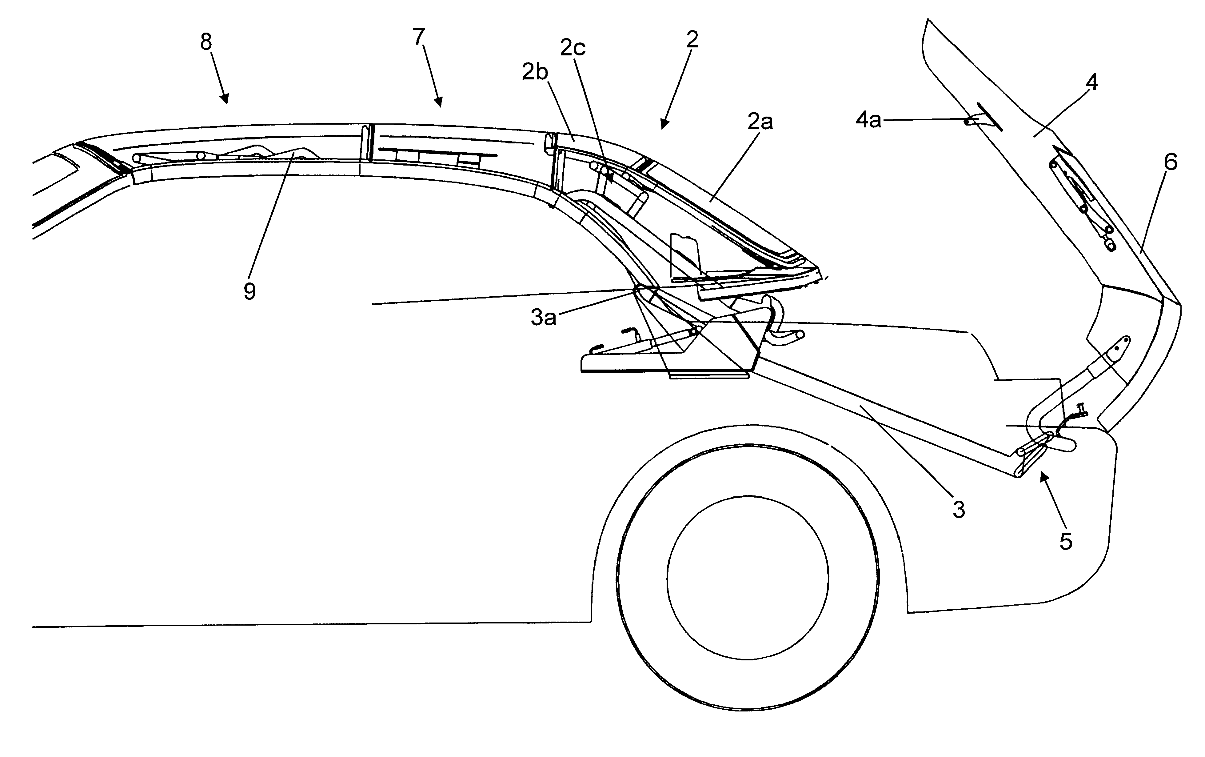
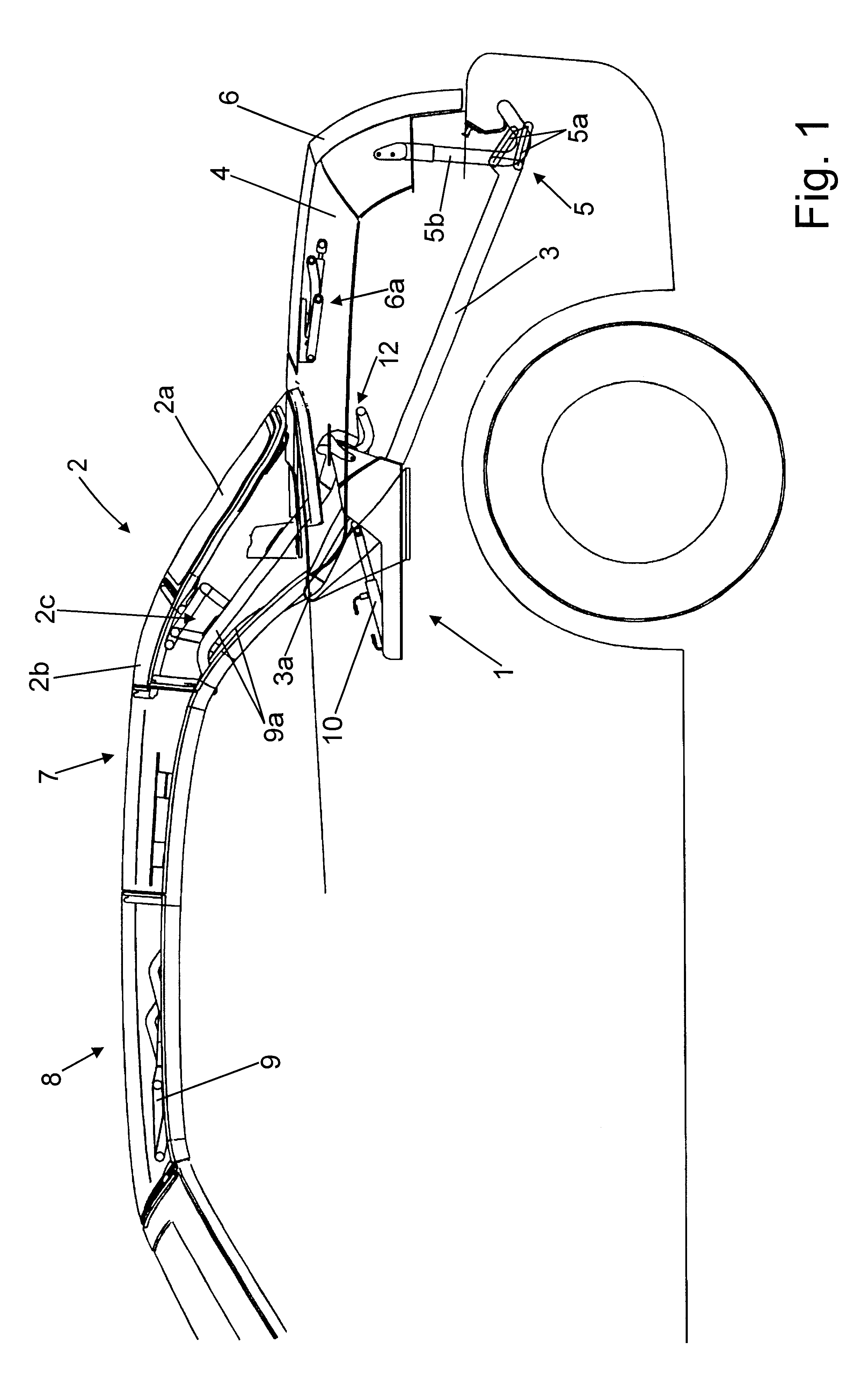
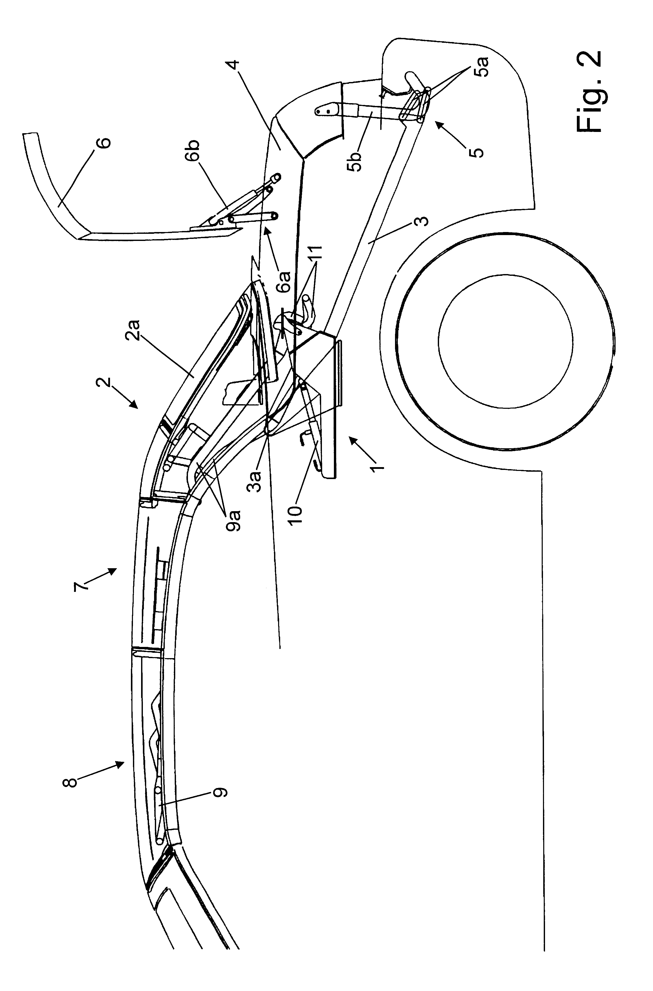
As shown in FIG. 1, a top according to the invention comprises a roof part 2 with a rigid rear window 2a fixed pivotably on the latter and a further roof segment 2b, which can be pivoted out, a central roof part 7 and a front roof part 8, all the roof parts being connected to one another in a positively controlled manner by means of a linkage 9. In particular, the linkage 9 comprises two main links 9a, which are pivotally connected to a main bearing 1 at a distance apart and can be driven by means of a driving device 12 comprising a hydraulic cylinder 10 and a link mechanism 11. The two main links 9a are connected to the roof segment 2b and the rigid rear window 2a by a four-bar rear-window linkage 2c. The roof part 2 is firmly connected to one of the main links 9a.

The main bearing 1 is firmly connected to a frame element 3, on which a rear element 4 is furthermore pivotably fixed by means of a rear bearing 5.

In this case, the frame element 3 can be pivoted relative to the vehicle a...


PUM


Abstract

A top for a convertible vehicle, comprising a roof part, said roof part at least partially covering the vehicle in a closed state and being pivotable about a main bearing; a frame element, said frame element being arranged in a rear area of the vehicle; a rear element, said rear element at least partially covering said rear area of the vehicle in a closed state, and a loading lid; said rear element being fixed on said frame element, in such a way as to be pivotable relative to said frame element, by means of a rear bearing arranged at a distance from said main bearing; said frame element being fixed on the vehicle in such a way as to be pivotable relative to the vehicle about an axis arranged in the region of said main bearing; said roof part being pivotable relative to the vehicle about said axis together with the frame element in an open, deposited position of said roof part; said main bearing being firmly connected to said frame element, and said loading lid being fixed on the rear element in such a way as to be pivotable relative to the rear element.

Description

The invention relates to a top for a convertible vehicle, comprising a roof part, said roof part at least partially covering the vehicle in a closed state and being pivotable about a main bearing, a frame element, said frame element being arranged in a rear area of the vehicle, a rear element, said rear element at least partially covering said rear area of the vehicle in a closed state, and a loading lid, said rear element being fixed on said frame element, in such a way as to be pivotable relative to said frame element, by means of a rear bearing arranged at a distance from said main bearing, said frame element being fixed on the vehicle in such a way as to be pivotable relative to the vehicle about an axis arranged in the region of said main bearing.DESCRIPTION OF THE PRIOR ARTIn the construction of modern convertibles, increasing use is being made of more complex convertible tops, which are constructed, in particular, as multi-part hard-shell folding tops. Since such folding tops...

Claims


Application Information

Patent Timeline
Patent Type & Authority Patents(United States)
IPC IPC(8): B60J7/00B60J7/20B60J7/08B60J7/14
CPCB60J1/1823B60J7/145B60J7/205B60J7/208
Inventor OBENDIEK, KLAUS
Owner WEBASTO EDSCHA CABRIO
Why Eureka
Try Eureka