Power supply noise sensor

a technology of power supply and noise sensor, applied in the direction of electric variable regulation, process and machine control, instruments, etc., can solve the problems of inability to forecast, most erroneous operation of digital systems, and damage to the digital circui

Inactive Publication Date: 2003-08-12
NEC CORP
View PDF7 Cites 10 Cited by
  • Summary
  • Abstract
  • Description
  • Claims
  • Application Information

AI Technical Summary

Benefits of technology

In accordance with the present invention, there is provided a power supply noise sensor, comprising a noise sensing section for sensing impulse noise applied to a power supply line; and an output holding section for holding a sense output from said noise sensing section, said noise sensing section including a time constant circuit for gradually varying a power supply voltage including impulse noise, wherein when a peak value of the impulse noise reduces after the peak value exceeds a predetermined value, a direction of a current flowing through said time constant circuit is inverted to hold a noise output from said output holding section also after the impulse noise disappears. Therefore, the impulse noise superimposed onto the power supply line can be appropriately sensed, and hence each circuit can be easily protected.
Moreover, in said power supply noise sensor, said noise sensing section comprises a first resistor, a second resistor, and a third resistor connected in series between a power supply terminal and ground; a capacitor forming said time constant circuit together with said first and second resistors, said capacitor being connected in parallel to said second resistor; and a first transistor including a base, a collector, and an emitter, the base being connected to a connecting point between said second and third resistors, the collector being connected via a fourth resistor to said power supply terminal, said emitter being connected to ground. In consequence, the noise sensor can be implemented in a simple circuit configuration.
Additionally, in said power supply noise sensor, said output holding section comprises a fifth resistor and a sixth resistor connected in series between ground and a connecting point between said fourth resistor and the collector of said first transistor; and a second transistor including a base, a collector, and an emitter, the base being connected to a connecting point between said fifth and sixth resistors, the collector being connected to a connecting point between said first and second resistors, said emitter being connected to ground. As a result, the noise sensing and holding operation can be achieved using a simple circuit configuration.
Furthermore, in said power supply noise sensor, a base current of said first transistor is larger after the sensing of the impulse noise than before the sensing thereof. Therefore, the noise can be sensed with higher reliability.

Problems solved by technology

However, when the noise exceeds a limit value of error acceptable (noise immunity) for the digital circuit, a fatal error possibly occurs to considerably damage the digital circuit in some cases.
On the other hand, most erroneous operations of digital systems are caused by noise entering from a signal line and a power supply line.
Particularly, when noise enters a digital circuit from a power supply side, it cannot be forecasted that an output is at a high (H) level or a low (L) level.
This makes it more difficult to appropriately cope with the noise.
However, the power supply noise similarly causes an erroneous operation also in the backup system, and hence the backup system does not satisfactorily function to implement a fail-safe system depending on cases.
However, there remain problems that the "power supply monitor circuit" detects a variation in a power supply signal with a relatively low frequency, and on the other hand, the flip-flop circuit of the "power supply noise detector circuit" may conduct an erroneous operation when power supply noise is received.
Moreover, either one of the above techniques to detect power supply noise is attended with a problem that the circuit configuration becomes complex.
Therefore, the technique to cope with the impulse noise in only one direction, namely, the negative or positive direction cannot be satisfactory in practical applications.

Method used


Image

  • Power supply noise sensor
  • Power supply noise sensor
  • Power supply noise sensor

Examples


Embodiment Construction

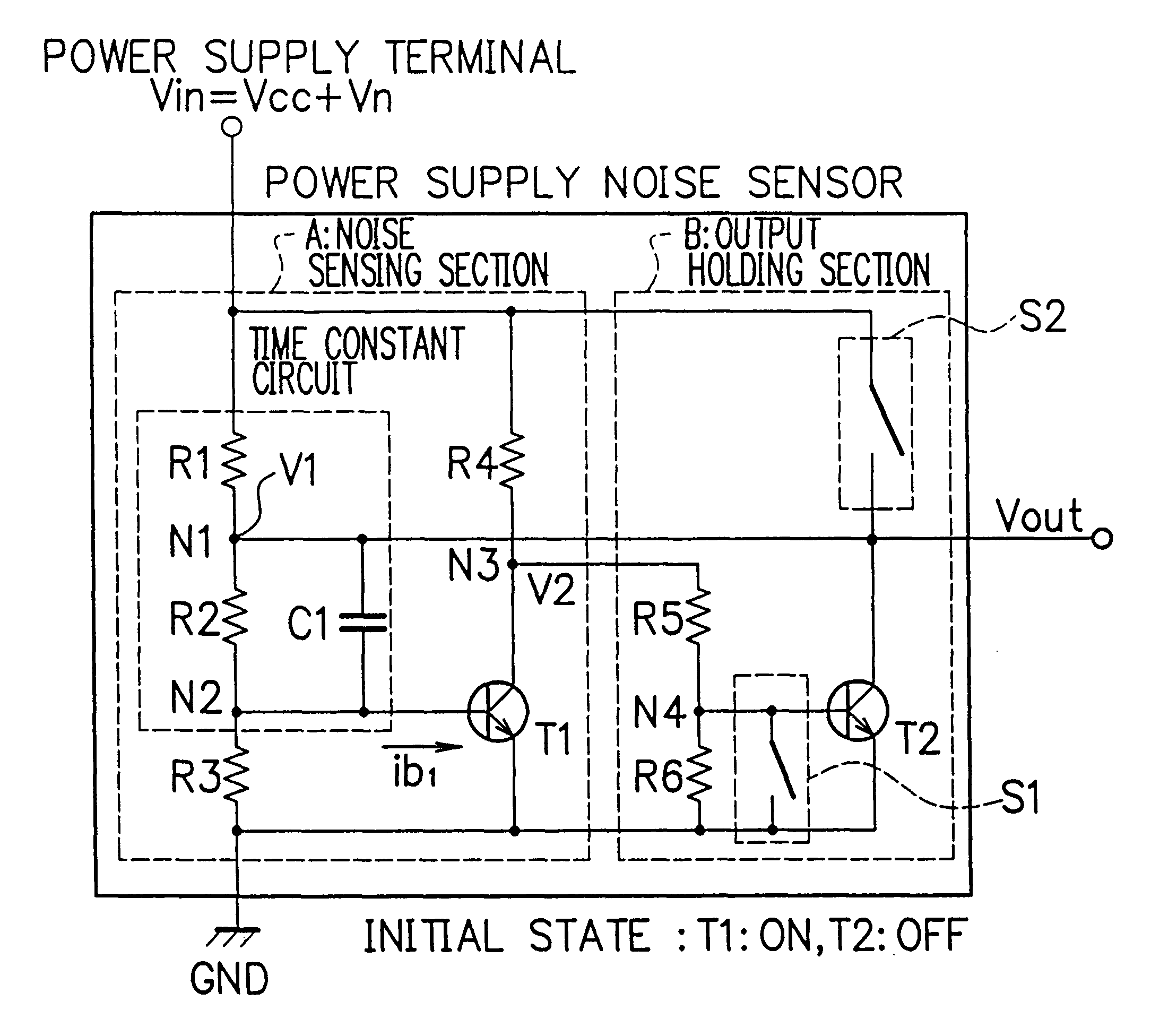
Referring next to the accompanying drawings, description will be given of an embodiment in accordance with the present invention. As can be seen from FIG. 1, the power supply noise sensor includes a noise sensing section A to sense impulse noise applied to a power supply line of the sensor and an output holding section B to hold an output which is a signal sensed by the noise sensing section A. The section A has an aspect that its time constant circuit dominates a transient response of a base current of a transistor in association with a power supply noise. That is, the time constant circuit includes a resistor R1 as a first resistor disposed between a power supply terminal of a power supply voltage Vcc and a node N1 and a parallel circuit including a resistor R2 as a second resistor arranged between the node N1 and a node N2 and a capacitor C1. The power supply noise sensor includes a transistor T1 having a base, a collector, and an emitter. The node N2 of the time constant circuit...


PUM


Abstract

A power supply noise sensor includes a noise sensing section A to sense impulse noise applied to a power supply line and an output holding section B to hold a sense output from the noise sensing section A. The noise sensing section A includes a time constant circuit to gradually vary a power supply voltage including impulse noise. When a peak value of the impulse noise reduces after the peak value exceeds a predetermined value, a direction of a current flowing through the time constant circuit is inverted to hold a noise output from the output holding section B also after the impulse noise disappears. Therefore, the impulse noise in the forward direction and the impulse noise in the reverse direction superimposed onto the power supply system of the sensor can be sensed in a simple configuration.

Description

The present invention relates to a power supply noise sensor for sensing impulse noise or glitch which causes, when applied to a power supply line of a digital system, an erroneous operation in the digital system.DESCRIPTION OF THE PRIOR ARTDigital systems including digital circuits have been today put to use in various fields. It generally considered that a digital circuit is more resistive against noise than an analog circuit. However, when the noise exceeds a limit value of error acceptable (noise immunity) for the digital circuit, a fatal error possibly occurs to considerably damage the digital circuit in some cases. On the other hand, most erroneous operations of digital systems are caused by noise entering from a signal line and a power supply line. Reference is to be made to "Noise of Control Devices and Countermeasure against Noise" written in IEEJ Technical Report II, No. 123 published in 1979.Particularly, when noise enters a digital circuit from a power supply side, it ca...

Claims


Application Information

Patent Timeline
Patent Type & Authority Patents(United States)
IPC IPC(8): G01R19/165H04B15/00G01R29/00G05F1/10
CPCG01R19/16552H04B15/005
Inventor TSUKAGOSHI, TSUNEONITTA, SHUICHI
Owner NEC CORP
Why Eureka
Try Eureka