Eureka AIR delivers breakthrough ideas for toughest innovation challenges, trusted by R&D personnel around the world.

Adjustable ratio control system and method

Inactive Publication Date: 2003-08-26
SECOWARWICK
View PDF7 Cites 5 Cited by
  • Summary
  • Abstract
  • Description
  • Claims
  • Application Information

AI Technical Summary

Problems solved by technology

There have been serious problems encountered in the annealing of some types of coiled material, such as light aluminum stock.
Because of the requirements of the heat treating cycle and the characteristics of the material in the coil form, the conventional annealing furnaces which have been used for this task have been found to be unsatisfactory.
While aluminum is essentially a good conductor of heat, it has been found that the coiled aluminum presents serious problems as far as conducting heat from the exterior to the interior portions of the coil.
The adjacent layers of aluminum present obstacles to conduction of heat radially through the coil.
Because the interior of the aluminum coil is more or less insulated from the exterior, it has been found to be very difficult to raise the temperature of the entire coil equally to the desired target temperature.
If the heating is performed too rapidly, the interior of the coil will lag far behind the exterior temperature.
One drawback in using the thermocouple giving the highest work temperature is that thermocouples for other coils giving a cooler work temperature require a longer period of time to reach the desired target temperature, i.e., Tann.
The furnace is thus operated for longer periods of time, thereby increasing furnace operating expenses.

Method used


Image

  • Adjustable ratio control system and method
  • Adjustable ratio control system and method
  • Adjustable ratio control system and method

Examples


first embodiment

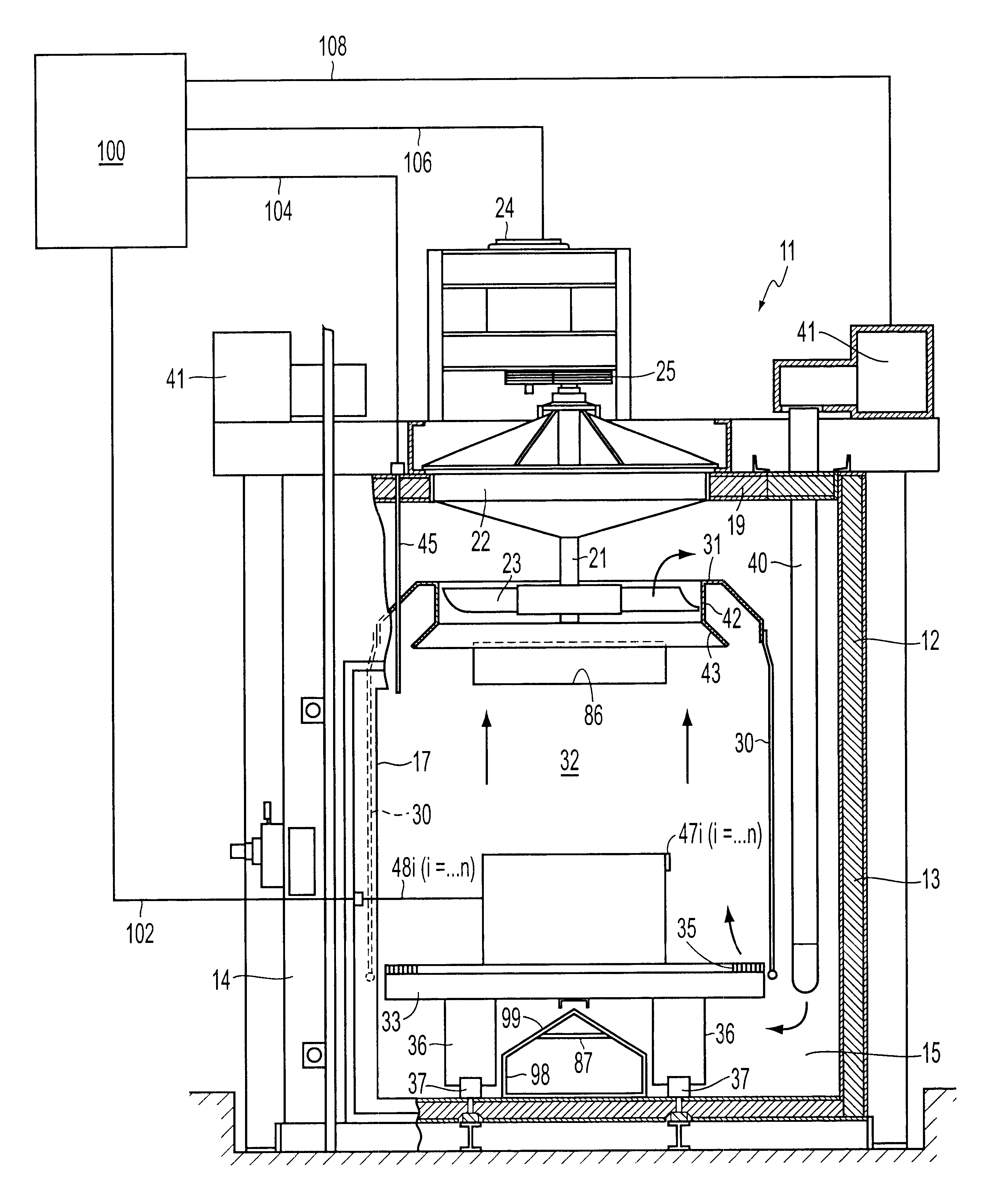
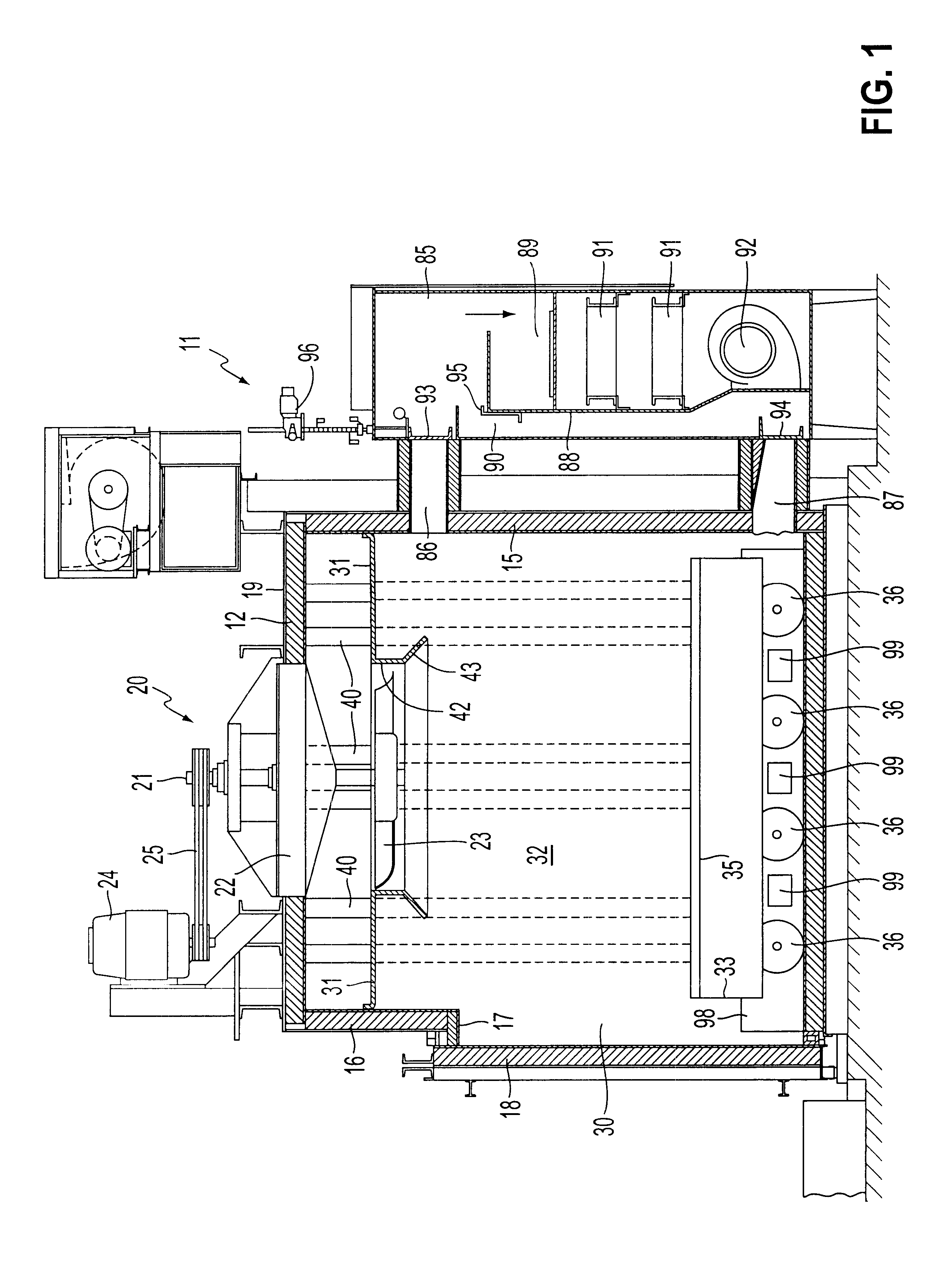
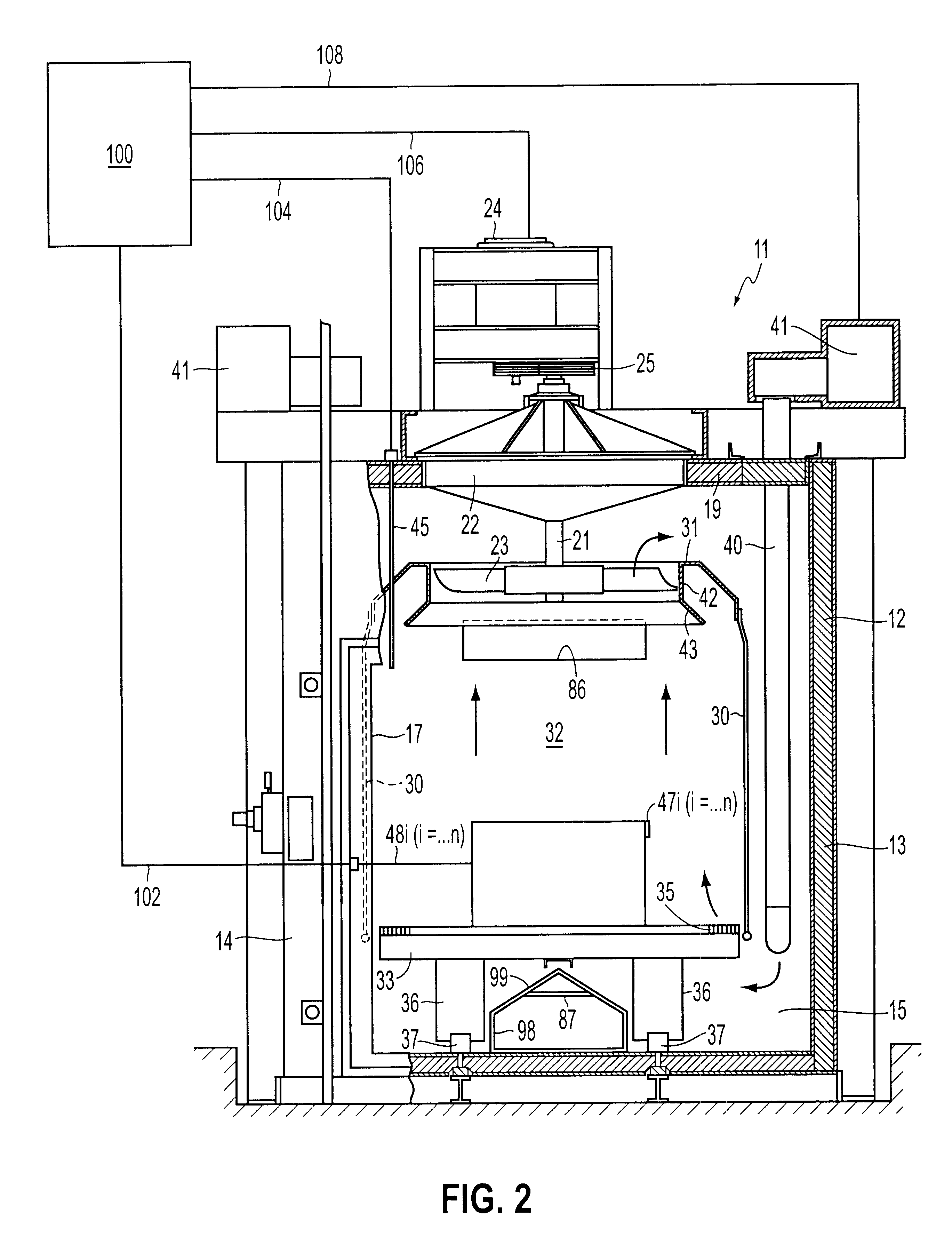
FIGS. 3 and 4 are flowcharts outlining a first embodiment for performing adjustable ratio control. In FIG. 3, the largest temperature differential from among the various zones is determined. FIG. 4 is a flowchart outlining the control process for implementing the adjustable ratio control using the maximum temperature differential determined in FIG. 3.

FIG. 3 is an embodiment for determining the largest .DELTA.t among the various zones. The operation begins at step S100 and proceeds to step S110. In step S110, the largest temperature differential .DELTA.t is determined from among the plurality of zones. Then, in step S120, the largest temperature differential is set as the maximum temperature differential .DELTA.tmax. Thereafter, the operation ends at step S130.

FIG. 4 is a flowchart outlining the control process for implementing the adjustable ratio control according to the first embodiment of the invention. The operation begins at step S200 and proceeds to step S210 where the tempera...

second embodiment

FIG. 5 is a flowchart outlining the control process for implementing the adjustable ratio control according to the invention using the maximum temperature differential determined in FIG. 3. The operation begins at S300 and proceeds to step S310 where a temperature differential .DELTA.t of a zone is retrieved.

In step S320, a determination is made as to whether the current temperature differential .DELTA.t, is greater than or equal to the maximum temperature differential .DELTA.tmax. If the temperature differential .DELTA.t is greater than or equal to the maximum temperature differential .DELTA.tmax, the operation proceeds to step S330. Otherwise, the operation proceeds to step S340 where the air set point AIR SP is the same as the work set point WSP. Thus, the air temperature set point AIR SP within the zone is the same as the annealing temperature of the coil because the adjustable ratio Ra is set to zero. In this embodiment, the coils with the lowest thermocouple reading are raised...

third embodiment

FIGS. 6 and 7 are flowcharts outlining a third embodiment for performing adjustable ratio control. In FIG. 6, the largest temperature differential from among the various zones and corresponding work temperature of the zone with the largest temperature differential is determined. FIG. 7 is a flowchart outlining the control process for implementing the adjustable ratio control using the maximum temperature differential and work temperature determined in FIG. 6.

FIG. 6 is a flowchart outlining another control process for implementing the adjustable ratio control similar to the flowchart of FIG. 3. However, in this embodiment, the work temperature WT for the zone with the largest temperature differential is set as the minimum work temperature Wtmin. The operation begins at step S400 and proceeds to step S410 and step S420 similar to steps S110 to S120 of FIG. 3. However, in step S430, the work temperature WT of the zone with the maximum temperature differential .DELTA.tmax is set as the ...


PUM

PropertyMeasurementUnit
Temperatureaaaaaaaaaa
Ratioaaaaaaaaaa

Abstract

Systems and methods for performing adjustable ratio control for a furnace with a plurality of workpieces located within a furnace and a sensor for determining the temperature of each of the workpieces. Adjustable ratio control is performed by controlling the temperature of an atmosphere of the furnace wherein a first workpiece with a lower temperature is heated at a higher rate than a second workpiece with a higher temperature.

Description

1. Field of InventionThe invention relates generally to a heat treating furnace for the annealing of workpieces. More particularly, the invention relates to a system and method for annealing a workpiece with accurate temperature control and uniformity.2. Description of Related ArtThere have been serious problems encountered in the annealing of some types of coiled material, such as light aluminum stock. Because of the requirements of the heat treating cycle and the characteristics of the material in the coil form, the conventional annealing furnaces which have been used for this task have been found to be unsatisfactory. The heat treating cycle requires that the aluminum be raised to a fairly specific temperature, such as 700.degree. F., and soaked at that temperature for a substantial period of time. It is important that the material not be heated higher than the target temperature because various types of deterioration occur at these elevated temperatures. Accordingly, it is the o...

Claims


Application Information

Patent Timeline
IPC IPC(8): C21D11/00F27D15/00F27D23/00F27D21/00F27D19/00F27B17/00F27D3/12F27D15/02F27D7/04F27D7/00F27D7/02C21D9/54C21D9/663C21D1/34C21D1/53F27D99/00
CPCC21D11/00F27B17/0083F27D3/123F27D7/02F27D7/04F27D15/02F27D19/00F27D21/0014F27D99/0001C21D1/53C21D9/663F27D99/0033F27D2019/0018F27D2019/0028F27D2019/0034F27D2099/0065
Inventor LARKO, ROBERT C.
Owner SECOWARWICK
Why Eureka
Eureka Blog
Learn More