Homo-code continuity proof testing device

a testing device and homo-code technology, applied in the direction of error prevention, digital transmission, instruments, etc., can solve the problems of inability to ensure the synchronization of detection of test data, the inability to determine the strength of homo-code continuity proof with high accuracy, and the complexity of the circui

Inactive Publication Date: 2003-08-26
FUJITSU LTD
View PDF4 Cites 24 Cited by
  • Summary
  • Abstract
  • Description
  • Claims
  • Application Information

AI Technical Summary

Problems solved by technology

Therefore, there is a problem that the homo-code continuity proof strength can not be determined with a high accuracy.
Namely, different from the prior art reset type of scrambling method in which the scrambling starting phase and the then initial value are predetermined periodically, the value of the shift register is not specified in the scrambler circuit

Method used


Image

  • Homo-code continuity proof testing device
  • Homo-code continuity proof testing device
  • Homo-code continuity proof testing device

Examples


Embodiment Construction

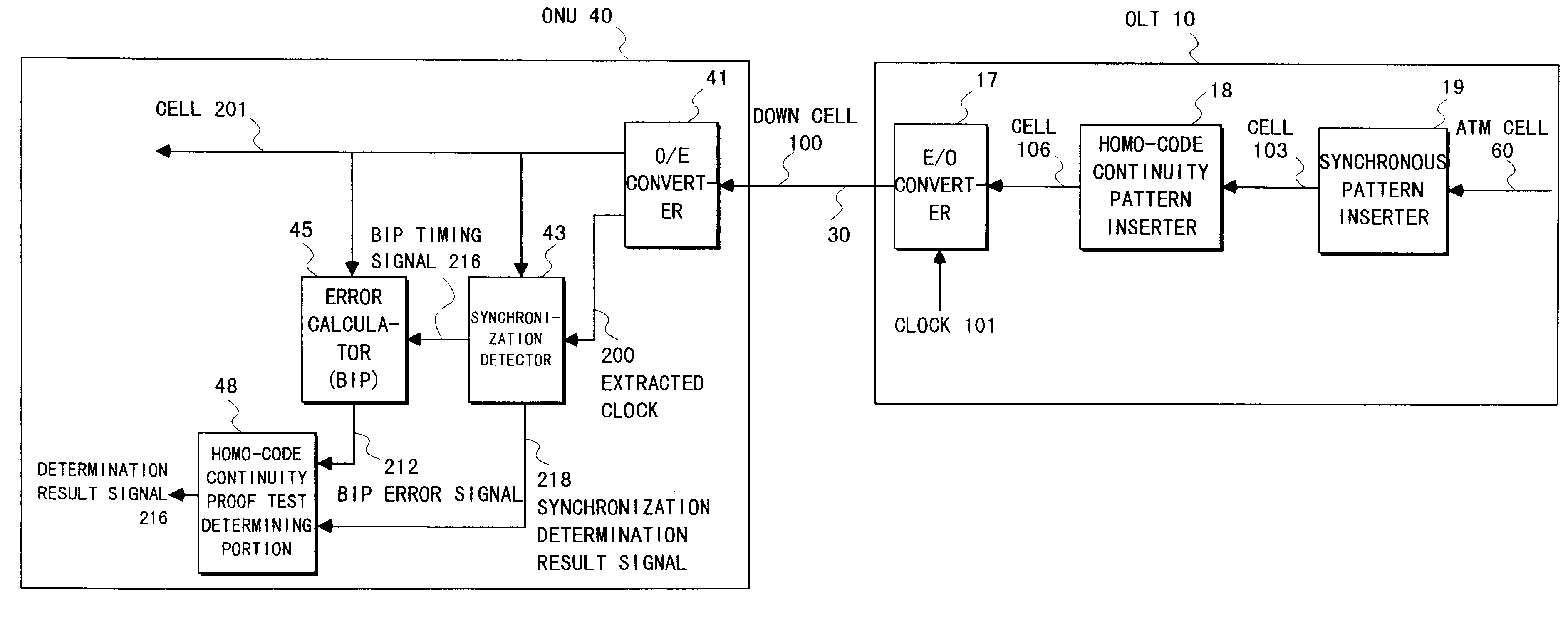
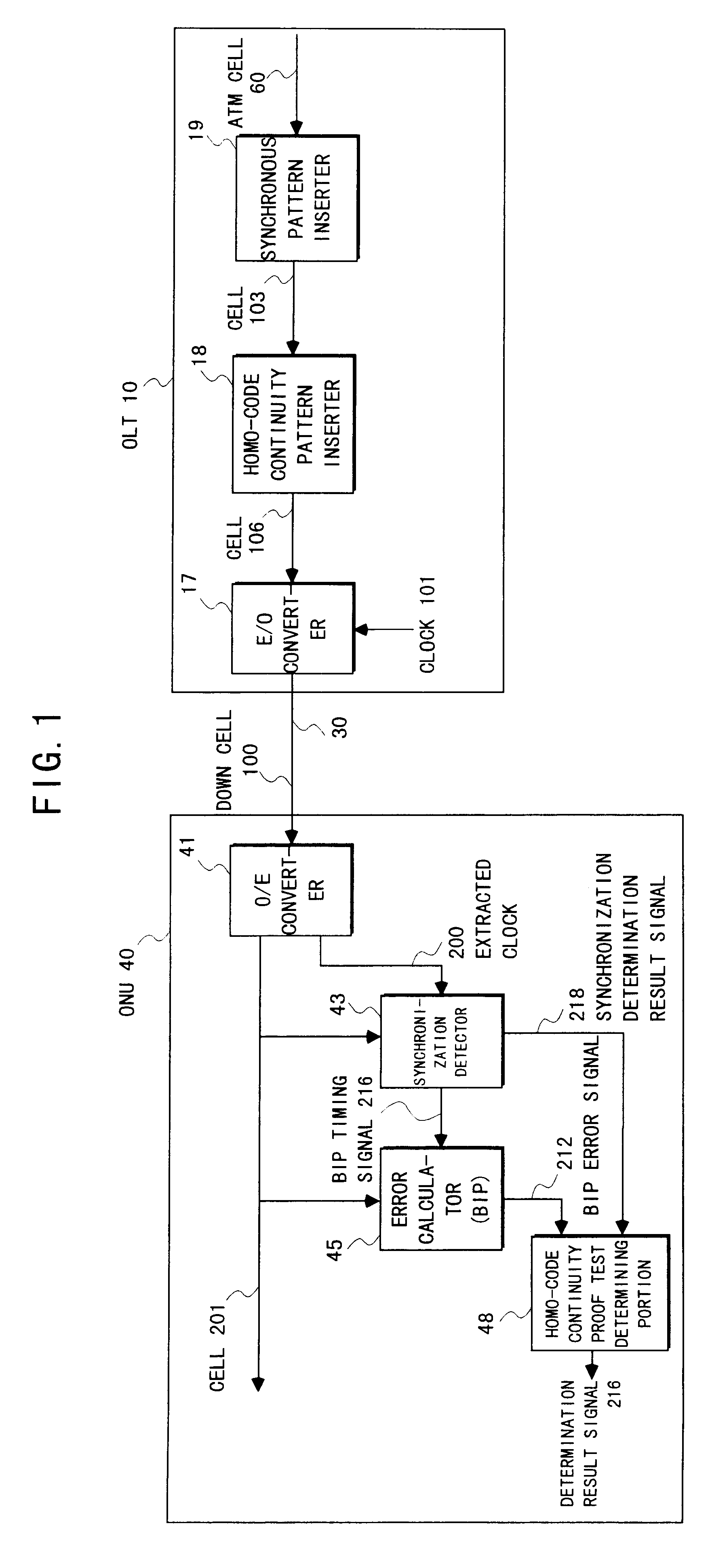
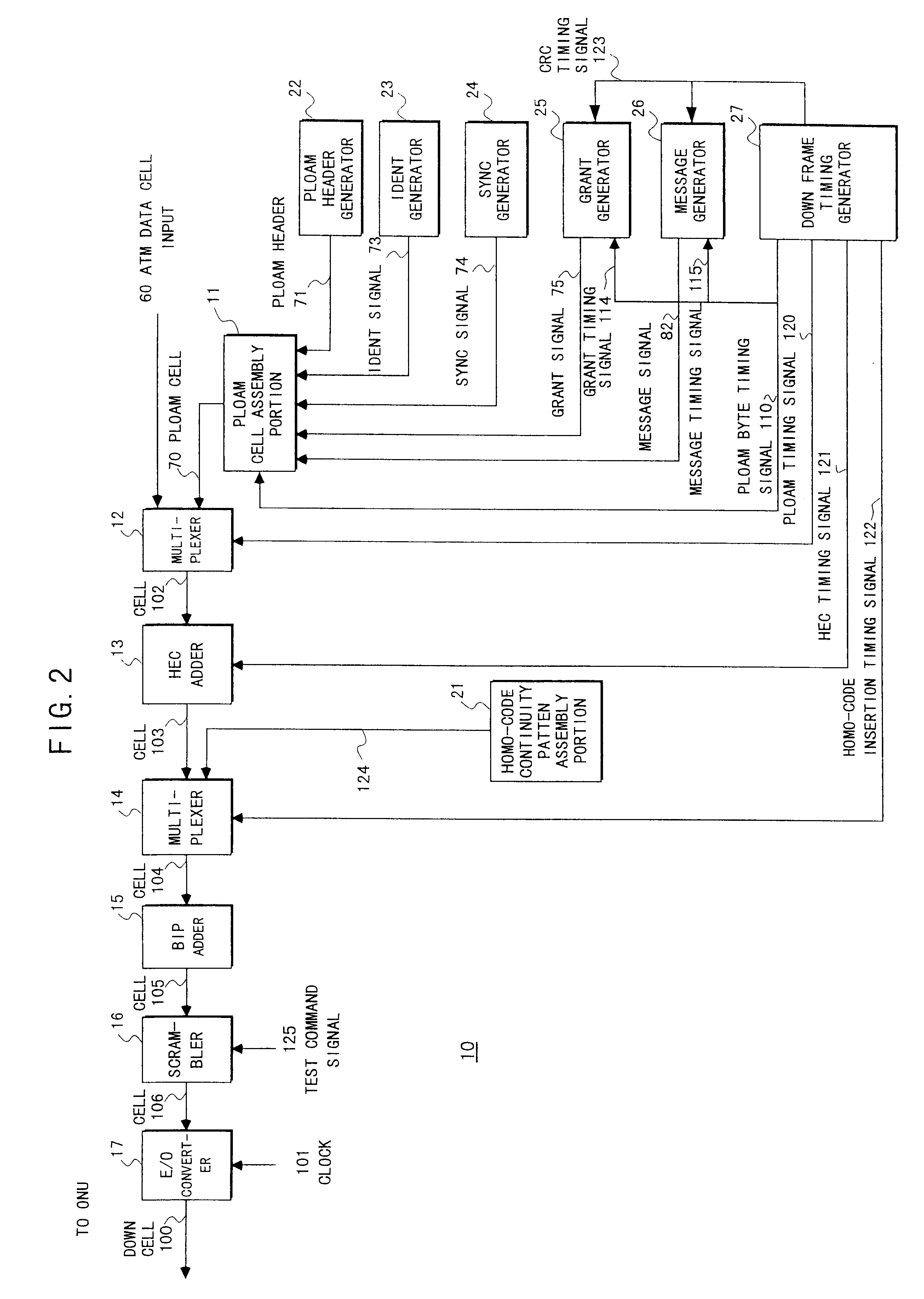
FIG. 2 shows an embodiment of the OLT 10 composing a homo-code continuity proof testing device according to the present invention. This OLT 10 includes a multiplexer 12 for outputting a cell or frame 102 (hereinafter, occasionally and simply referred to as cell) which is the ATM data cell 60 multiplexed with the PLOAM cell 70, an HEC adder 13 for outputting the cell 103 which is the cell 102 to which the HEC's 61_2 and 72 (see FIGS. 17A and 17B) are added, a multiplexer 14 for outputting, to the cell 103, a cell 104 into which a homo-code continuity proof test pattern signal 124 is inserted with a timing of a homo-code inserting timing signal 122, a BIP adder 15 for outputting a cell 105 to which the BIP calculation of the cell 104 is performed and the BIP 81 (see FIG. 17A) is added, a scrambler 16 for outputting a cell 106 which performs a distributed type of scramble to all bits of the whole cell 105, and the E / O converter 17 for synchronizing (multiplexing) the cell 106 with the ...


PUM


Abstract

In a homo-code continuity proof testing device for testing with test data including a predetermined homo-code continuity proof test pattern, a testing device on a transmitting side synchronizes the test data in the form of a frame, including a predetermined test pattern, a data synchronous pattern, an error detecting pattern, and preferably a frame synchronous pattern for testing a homo-code continuity proof strength, with a predetermined clock, to be transmitted. A tested device on a receiving side extracts a clock included in the test data, detects the data synchronous pattern, the error detecting pattern, and the frame synchronous pattern in synchronization with the extracted clock, and determines a homo-code continuity proof test by the detection/undetection of each pattern.

Description

1. Field of the InventionThe present invention relates to a homo-code (identical or same code) continuity proof testing device, and in particular to a homo-code continuity proof testing device which conducts tests with test data including a predetermined homo-code continuity proof test pattern.In recent years, a digital network has become rapidly widespread with the advance of an LSI technique, an optical fiber cable technique, a digital signal processing technique, and the like. For transferring a signal from a transmitting device to a receiving device in an asynchronous state in the digital network, there is a method wherein the receiving device extracts a clock included in a received signal to perform the receiving operation for the signal in synchronization with the extracted clock.When the received signal includes a continuous or sequential homo-code in this method, it is difficult for the receiving device to extract the clock. As a measure for this difficulty, the transmitting...

Claims


Application Information

Patent Timeline
IPC IPC(8): H04L1/24H04L1/00G06F11/22H04L7/00H04L69/40
CPCH04L1/242
Inventor FUJIYOSHI, SHINICHIUCHIDA, KAZUHIRORYU, KAZUYAHIRASHIMA, KATSUHIKOKOYANAGI, TOSHINORIABIRU, SETSUO
Owner FUJITSU LTD
Why Eureka
Try Eureka