Lighting system and device

a lighting system and lighting technology, applied in the field of lighting systems and devices, can solve the problems of inability to maintain the brightness of the light source, and inability to produce intensely visible light,

Inactive Publication Date: 2003-09-02
NEPIL JAMES
View PDF2 Cites 103 Cited by
  • Summary
  • Abstract
  • Description
  • Claims
  • Application Information

AI Technical Summary

Benefits of technology

A further object of the present invention is to provide a safe, reliable, durable, long lasting, and virtually unbreakable lighting device.
Another object of the present invention is to provide a lightweight device.
Yet another object of the present invention is to provide a lighting device with high energy efficiency--high light intensities generated by low power (AC or DC).
Further objects of the present invention are to provide a lighting device that has a long operational life--subject only to power supply; whose light emission continues indefinitely without chemical breakdown or materials fatigue; that is simple to construct with few parts to fail; and that is durable--water-submergible and shock-proof--virtually unbreakable in normal use.

Problems solved by technology

Many of the prior art lighting devices suffer from limitations, including that such devices are incapable of producing intensely visible light from many yards away, and that the few devices that are capable of producing such illumination are not durable or energy efficient.
Bulbs bum out, batteries weaken, water shorts electrical components, and housings break easily when dropped or jarred.
The bulb is mounted in an opaque section of the housing resulting in low light intensity.
Light production of the Cimock device is limited.
The device is not only an inadequate means of producing high intensity lighting, but it is also not durable because the glass housing will likely shatter if dropped.
However, this device is incapable of producing high-intensity lighting.
Furthermore, although both devices utilize fluid mediums, both require agitation to obtain the full effect of the fluid: the Orak device requires agitation to swirl the liquid colors and the Lew et al. device requires agitation to make the light reflecting particles move through the fluid.
Although this device is capable of producing visual signals of a particular light and of flashing color signals in a predetermined sequence, connecting the LEDs to wire rods is not as stable as connecting the LEDs to the structure of the device.
Thus, this device is not durable as a blow to the signal stick can disconnect one of the connections.
While these are toxic, they can be used with or without aqueous dilution with water.
It will be understood by those of skill in the art that ingredient concentrations can vary to produce different effects and intensities, although some combinations may have disadvantageous effects.
For example, as more color is used, the more likely it is to adhere to the LEDs, causing a rise in temperature.
The filament bulb of the Harris, Jr. device draws high power vs. that of the present devices' LEDs, but emits a much lower intensity of usable light.
Finally, the Harris, Jr. design has limited use, not the broad applications foreseen for the technology of the present application.
Further, only low light intensities are generated.

Method used


Image

  • Lighting system and device
  • Lighting system and device

Examples


Embodiment Construction

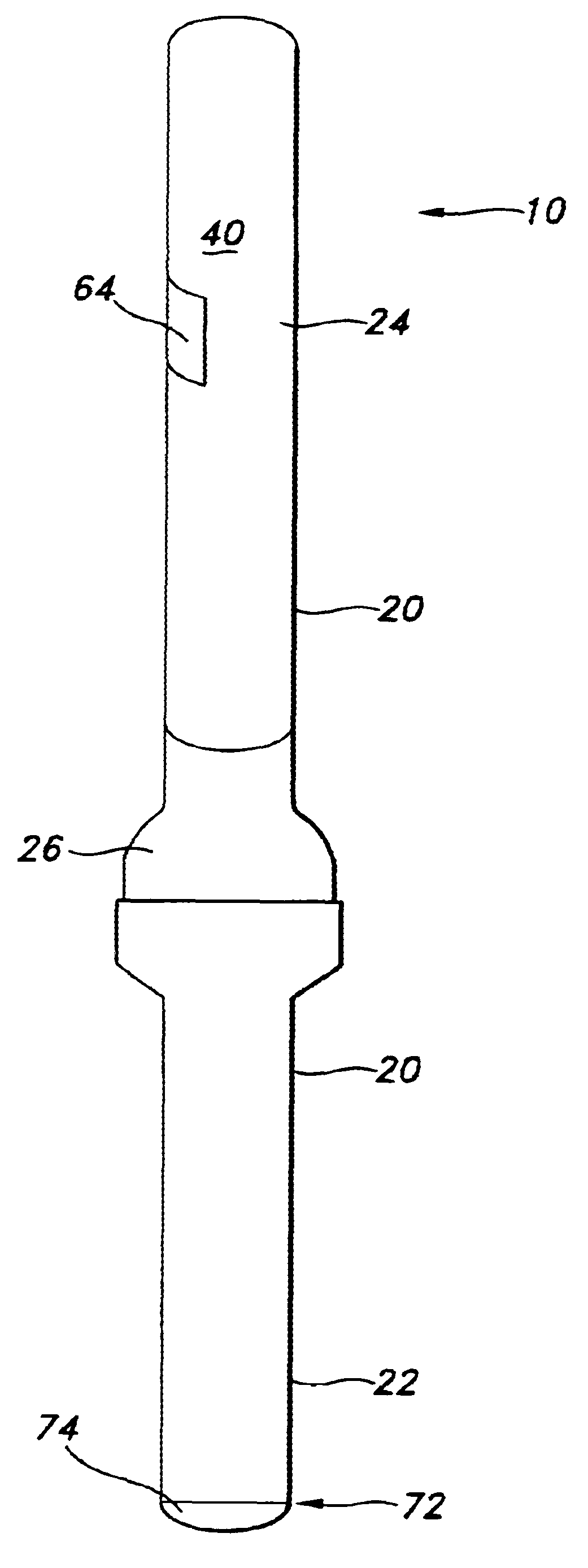
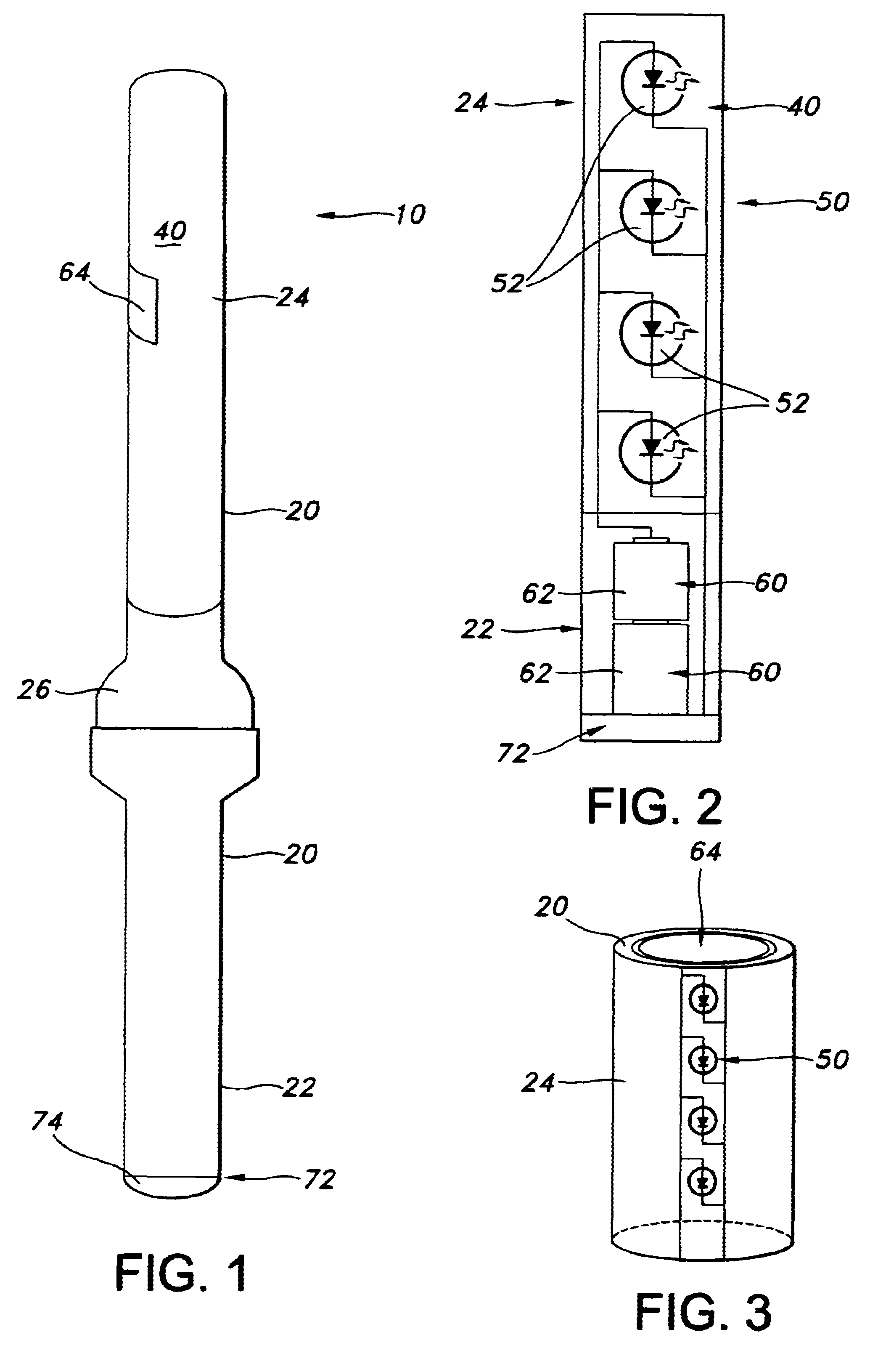
Referring now in detail to the drawing figures, wherein like reference numerals represent like parts throughout the several views, FIGS. 1-3 illustrates a preferred embodiment of the present invention 10. As shown, the present invention 10 comprises a housing 20, lighting fluid 40 carried within the housing 20, a light element 50 immersed in the lighting fluid 40, and a power source 60 to energize the light element 50. The present invention 10 is preferably lightweight and portable.

In a preferred embodiment, the housing 20 is a unitary columnar assembly formed of a durable, lightweight and water-resistant material that can withstand shock if dropped. The assembly has at least one section 24 through which light can pass, and wherein the material of this section preferably is not adversely affected by gas, oil, ether, or most other organic solvents. One such material is plastic. In one preferred embodiment, the housing 20 comprises a food grade plastic. Alternatively, as will be under...


PUM


Abstract

The present invention is a light-producing technology exemplified by lighting that is safe, reliable, energy efficient, long lasting, and capable of operating under a wide range of weather and other conditions. The device incorporates a durable housing, a light element, a liquid solution, and a power supply. Subject only to its power source, it is capable of indefinitely producing intensely visible light at 100 yards or more during both daytime and nighttime. It can be configured for higher or lower intensities in a wide variety of foreseen applications. The device is not flammable, explosive, or toxic, and without loss of function withstands shock, extended water immersion, and heating and cooling to temperatures below freezing and approaching boiling.

Description

1. Field of the InventionThe present invention relates generally to a novel lighting technology, and a lighting device incorporating such technology. The lighting device is a fluid-filled, hand-held signal light that is safe, durable, and energy efficient. The present lighting device lends itself to a wide spectrum of indoor and outdoor applications.2. Description of Related ArtLighting devices are known that are used for both aesthetic and utilitarian purposes. Lighting devices conventionally comprise a housing containing a light element, a power source for the light element, and a medium through which the light travels from the light element to the exterior of the housing. For example, in a flashlight, the light element is a light bulb, the power source a couple of batteries, and the medium is air between the light bulb and the clear plastic cover.Many of the prior art lighting devices suffer from limitations, including that such devices are incapable of producing intensely visibl...

Claims


Application Information

Patent Timeline
Patent Type & Authority Patents(United States)
IPC IPC(8): F21S10/00F21L4/00F21L4/02F21V15/04F21V15/00
CPCF21L4/027F21S10/002F21V15/04F21Y2101/02Y10S362/806F21Y2115/10
Inventor NEPIL, JAMES
Owner NEPIL JAMES
Why Eureka
Try Eureka