Endovascular aneurysm embolization device

a technology of embolization device and endovascular aneurysm, which is applied in the field of medical devices, can solve the problems of inability to access the tortuous vascular anatomy of the vascular anatomy, inability to complete aneurysm embolization,

Inactive Publication Date: 2003-09-02
CODMAN & SHURTLEFF INC
View PDF26 Cites 375 Cited by
  • Summary
  • Abstract
  • Description
  • Claims
  • Application Information

AI Technical Summary

Problems solved by technology

These balloons do not generally conform to the aneurysm space thereby leaving unoccupied space leading to an incomplete aneurysm embolization.
Often times a balloon valve may leak thereby causing other balloons to shift position, which may in turn, occlude the parent artery leading to se...

Method used


Image

  • Endovascular aneurysm embolization device
  • Endovascular aneurysm embolization device
  • Endovascular aneurysm embolization device

Examples


Embodiment Construction

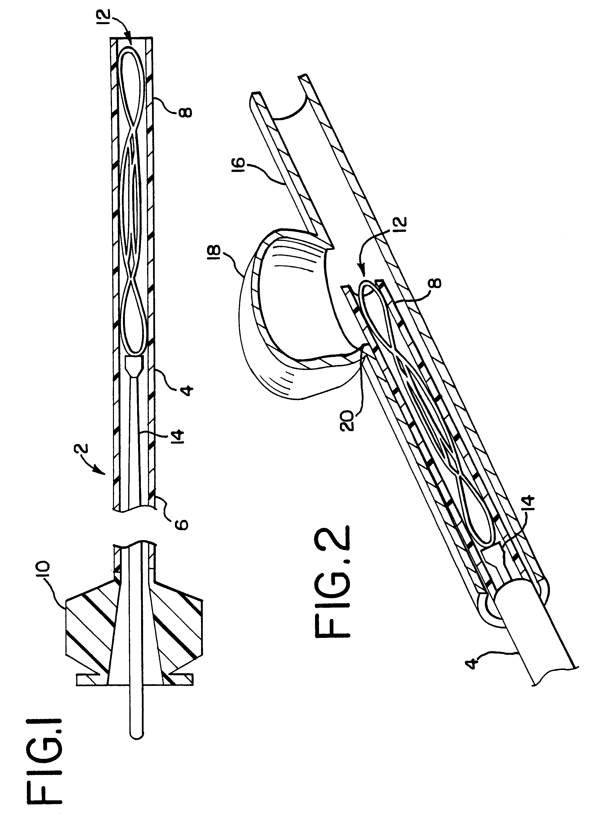
FIG. 1 generally illustrates the aneurysm embolization system 2 which is comprised of a catheter 4, having a proximal end 6 and a distal end 8, a hub 10 attached to the proximal end 6 of the catheter 4, and an aneurysm embolization device 12 slidably disposed within the lumen of the distal end 8 of catheter 4. The lumen of the hub 10 is in fluid communication with the lumen of the catheter 4. A push rod 14 is positioned through the lumen of the hub 10 and into the lumen of the catheter 4.

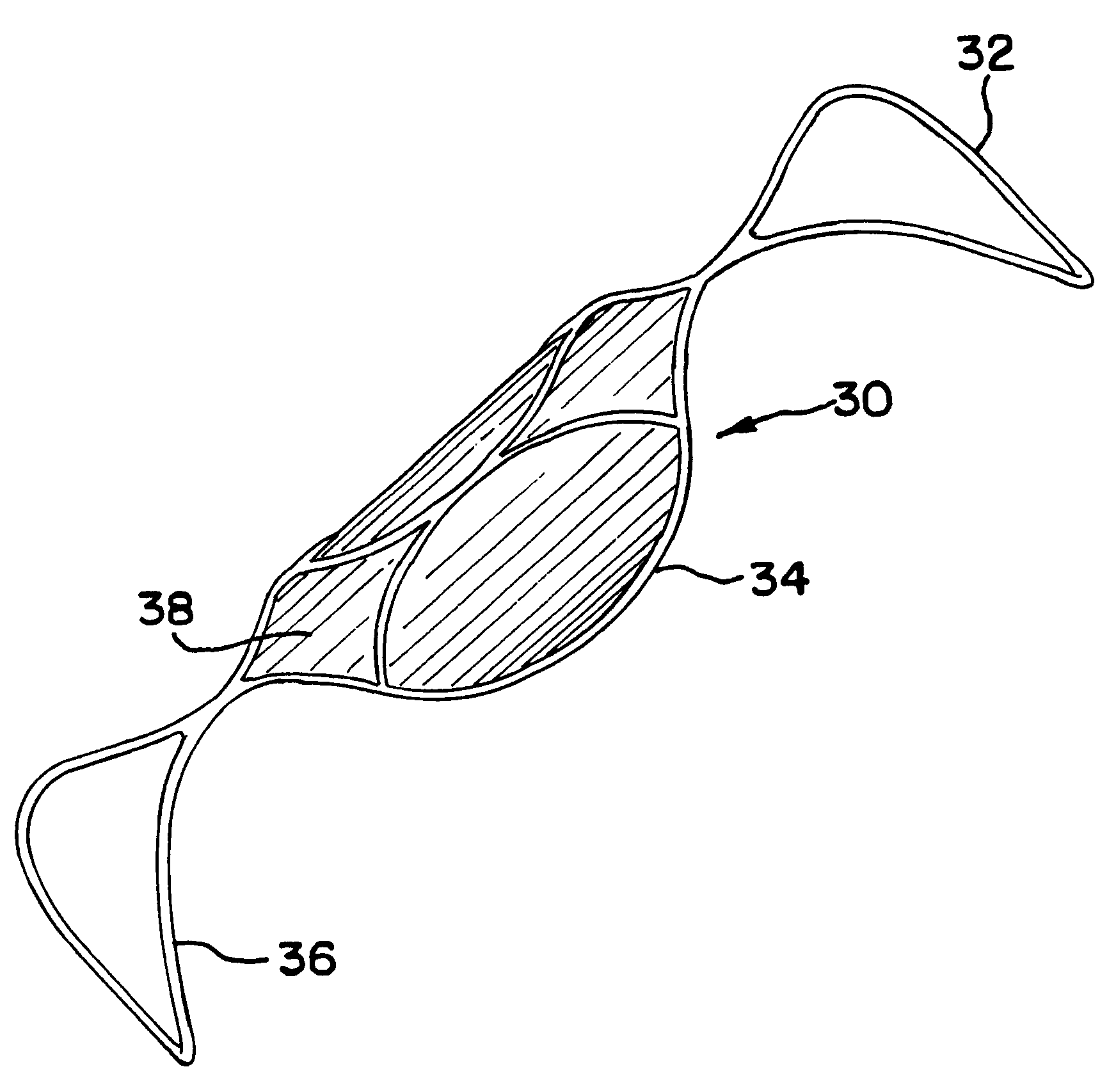
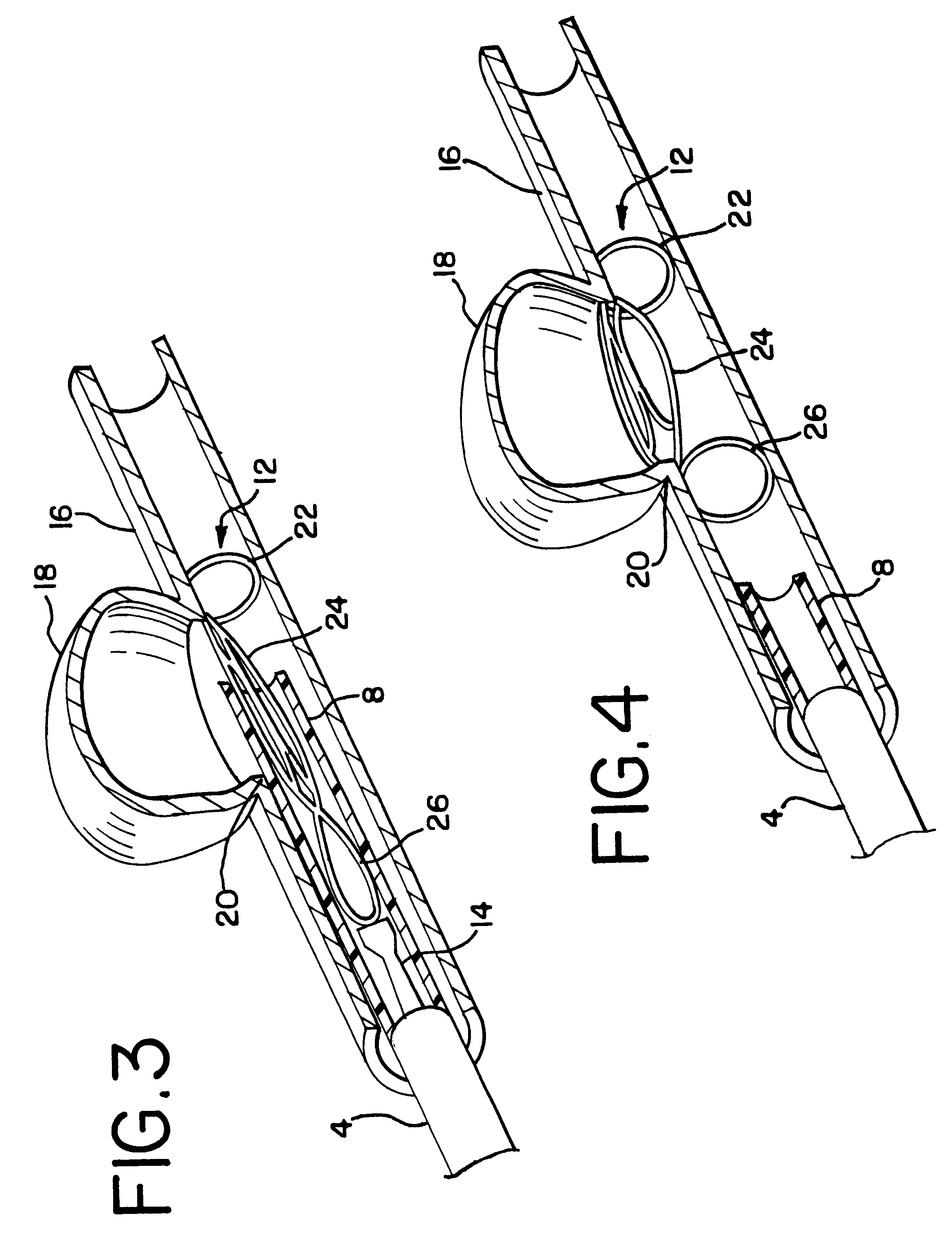
FIGS. 2, 3, and 4 show the sequential steps in deploying the aneurysm embolization device 12. FIG. 2 shows a partially sectioned view of the aneurysm embolization system 2 in a vessel 16. Vessel 16 contains an abnormal defect commonly referred to as an aneurysm 18. The point of origin of aneurysm 18 from the vessel 16 is commonly referred to as the aneurysm neck 20. FIG. 2 also illustrates the distal end 8 of catheter 4 in close proximity to the aneurysm neck 20. Collapsed within the lumen of the di...


PUM


Abstract

The present invention relates to a medical device for placement at a predetermined location within a vessel of the human body, and more particularly, relates to a collapsible aneurysm embolization device that is delivered through the lumen of a catheter and exits the catheter at a predetermined position within the vessel to thereby embolize a blood vessel defect, such as an aneurysm.

Description

1. Field of the InventionThe present invention relates to a medical device for placement at a predetermined location within a vessel of the human body, and more particularly, relates to a collapsible embolization device that is delivered by a catheter at a predetermined position within the vessel to thereby embolize a defect in the blood vessel, such as an aneurysm.2. Description of the Prior ArtFor many years flexible catheters have been used to place various devices within the vessels of the human body. Such devices include dilatation balloons, radiopaque fluids, liquid medications and various types of occlusion devices such as balloons and embolic coils. Examples of such catheter devices are disclosed in U.S. Pat. No. 5,108,407 to Geremia, et al., entitled, "Method And Apparatus For Placement Of An Embolic Coil" and U.S. Pat. No. 5,122,136 to Guglielmi, et al., entitled, "Endovascular Electrolytically Detachable Guidewire Tip For The Electroformation Of Thrombus In Arteries, Vein...

Claims


Application Information

Patent Timeline
IPC IPC(8): A61B17/12
CPCA61B17/12022A61B17/12118A61B17/1219A61B2017/1205A61F2002/823
Inventor MITELBERG, VLADIMIRMARTINEZ, SUSANA
Owner CODMAN & SHURTLEFF INC
Why Eureka
Try Eureka