Magnetic disk apparatus

a magnetic disk and apparatus technology, applied in the direction of instruments, recording information storage, support for heads, etc., can solve the problems of deteriorating the reliability of the magnetic disk apparatus, difficult to keep an appropriate flying height, and inability to record/record, etc., to achieve accurate positioning

Inactive Publication Date: 2003-09-02
WESTERN DIGITAL TECH INC +1
View PDF9 Cites 60 Cited by
  • Summary
  • Abstract
  • Description
  • Claims
  • Application Information

AI Technical Summary

Benefits of technology

An object of the present invention is to provide an actuator structure and a magnetic disk apparatus using the same that solves a

Problems solved by technology

Furthermore, the piezoelectric element is made of a brittle member, and therefore it has disadvantages that it is vulnerable to impacts and sliding and is likely to produce dust from the sliding portion or portions on which stress is concentrated at the time of receiving an impact or at the time of driving the piezoelectric element.
Therefore, if dust is produced, it becomes difficult to keep an appropriate flying height and it becomes impossible

Method used


Image

  • Magnetic disk apparatus
  • Magnetic disk apparatus
  • Magnetic disk apparatus

Examples


third embodiment

FIG. 9 and FIG. 10 are a perspective view and a side view showing a method of wiring to the microactuator 9, which is the present invention, and FIG. 11 shows a sectional view of the area adjacent to the mount, taken along line XI--XI in FIG. 9.

In FIG. 9 and FIG. 10, a flexure 2 provided with a wiring pattern from the magnetic head extends to the vicinity of the mount 5. Normally, the wiring pattern of the flexure 2 is structure by laminating a polyimide layer, which serves as an insulation layer, and a copper layer, which serves as signal lines on the flexure 2 made of stainless steel such as SUS304. Flexure 2 is fastened to a wiring fixing plate 13 and further electrically connected to a wiring portion 14. An FPC (flexible printed circuit board) is suitable for the wiring portion 14. The wiring portion 14 is provided with a terminal 15 and the terminal 15 and the upper electrode 13 of the microactuator 9 are electrically connected through a signal line 16.

With these structure, sig...

fourth embodiment

FIG. 18 shows a structure of a suspension support apparatus according to the present invention. FIG. 19 is a characteristic diagram showing an experimental measurement of the amplitude (dB) in Y-direction and the phase of the magnetic head 31 when the microactuator 9 is driven using the suspension shown in FIG. 18.

first embodiment

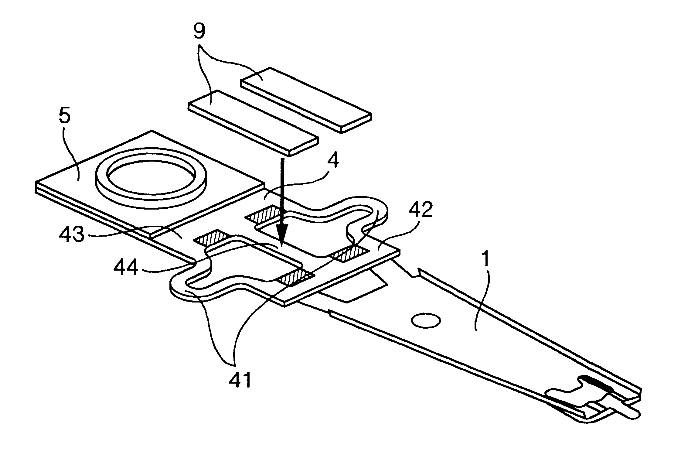
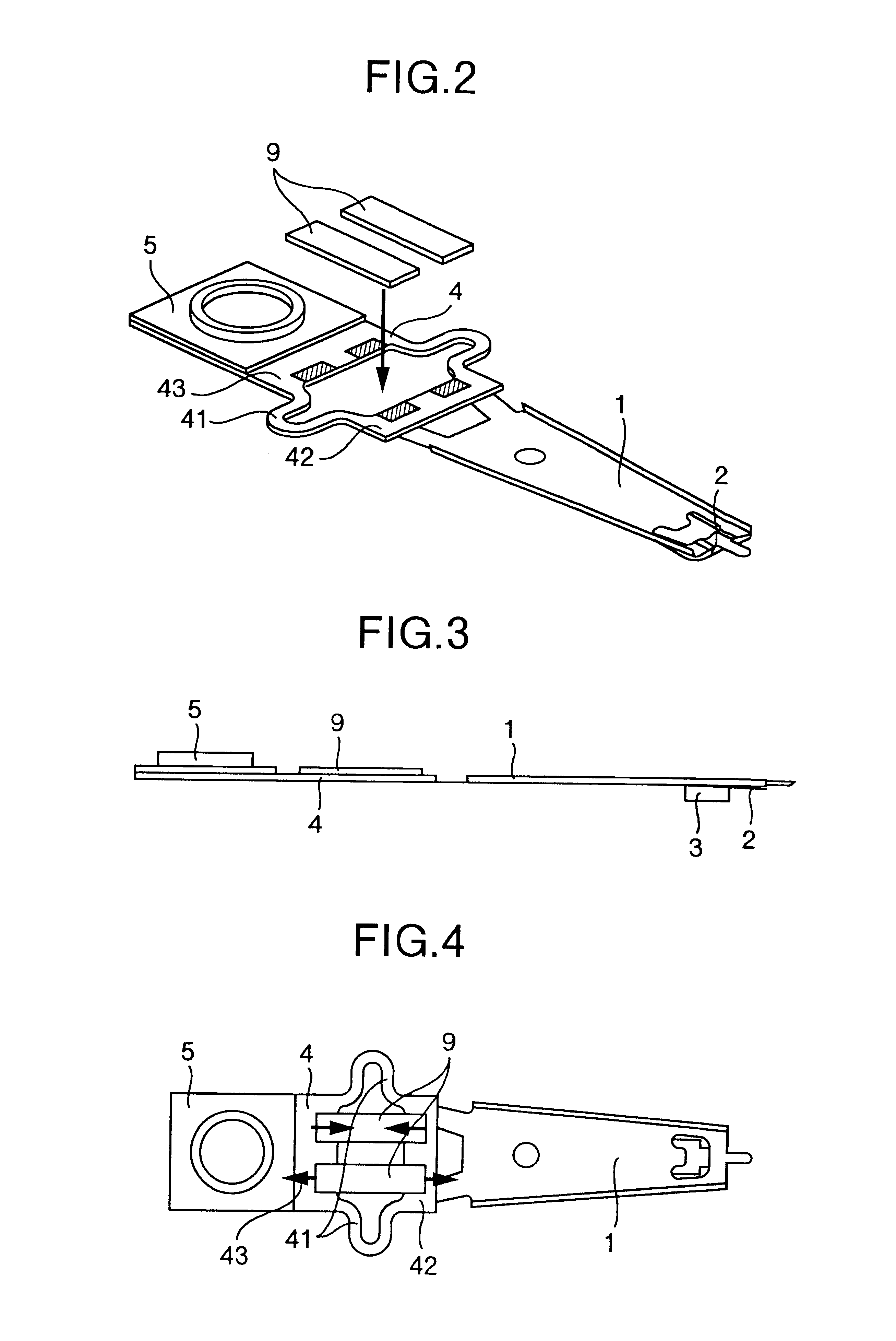
The fourth embodiment in FIG. 18 differs from the first embodiment in that bellows-figured arm portions 41a are provided in longitudinal direction of the suspension on both sides of the window portion 10 on the microactuator mounting portion 4. A part of the bellows-figured arm portion is protruded out of both sides of the microactuator mounting portion 4.

In the case where the position of the magnetic head is deviated from a predetermined track of the disk 8 after the voice coil motor is operated to position the magnetic head, this structure adjusts the position of the magnetic head by applying a voltage to the piezoelectric elements 9 to rotate the load beam 1, through extension and contraction of the piezoelectric elements 9, to move the magnetic head in the positioning direction.

For example, suppose the width d of the microactuator mounting portion 4=5.4 mm, thickness h=0.15 mm, length c of the window portion 10=3 mm, width w of bellows-figured arm portion 41a=0.4 mm, length a of...


PUM


Abstract

A magnetic disk apparatus of the present invention is equipped with a microactuator for micro motion using piezoelectric elements in addition to a coarse adjustment actuator such as a voice coil motor or the like, eliminates parts that slide between the microactuator and surrounding members, and alleviates stress on the piezoelectric elements even if an impact is given to the magnetic disk apparatus. Thus, a first actuator fixing portion on a carriage side and a second actuator fixing portion on a magnetic head side of a microactuator mounting portion are coupled with a plurality of flexible coupling portions and coupling portions are placed outside the microactuator in substantially symmetric with respect to a centerline in a longitudinal direction of a suspension.

Description

The present invention relates to a magnetic disk apparatus, and more particularly, to a head support mechanism incorporating a microactuator for precise positioning of a magnetic head on a target track and a magnetic disk apparatus using the same.With an increasing capacity of a magnetic disk apparatus in recent years, the magnetic head is required to perform extremely high precision positioning on a target track. Therefore, a drive mechanism has been proposed for a magnetic disk apparatus with a structure comprising a voice coil motor provided opposite to the magnetic head with respect to a carriage rotation center, which allows the magnetic head to move roughly, and an actuator for micro motion provided at a suspension.For example, JP-A-11-16311 discloses a structure in which a micro actuator is provided between a load beam and a suspension provided with a magnetic head in addition to a coarse adjustment actuator.Furthermore, JP-A-9-73746 discloses a head support apparatus compris...

Claims


Application Information

Patent Timeline
IPC IPC(8): G11B5/55G11B5/56
CPCG11B5/4833G11B5/486G11B5/4873G11B5/5552G11B5/4813G11B5/5582
Inventor SHIMIZU, TOSHIHIKOMASUDA, HIROMITSUNANIWA, IRIZOTOKUYAMA, MIKIONAKAMURA, SHIGEOWAKATSUKI, KOUSAKUTAKAHASHI, HARUHIDEODAI, MASAKI
Owner WESTERN DIGITAL TECH INC
Why Eureka
Try Eureka