

Telescopic vibration damper
- Summary
- Abstract
- Description
- Claims
- Application Information
AI Technical Summary
Benefits of technology
Problems solved by technology
Method used
Image

Examples
Embodiment Construction
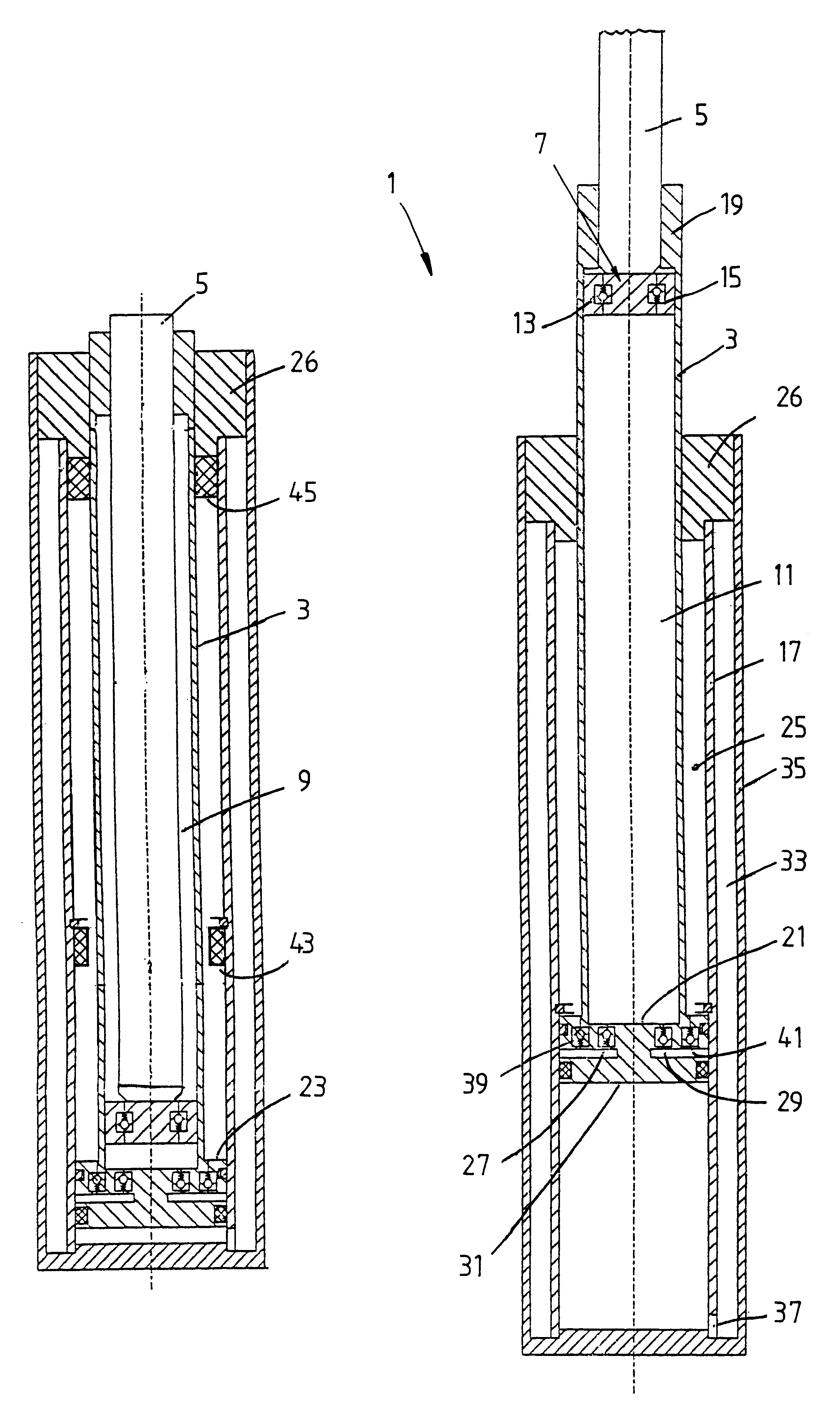
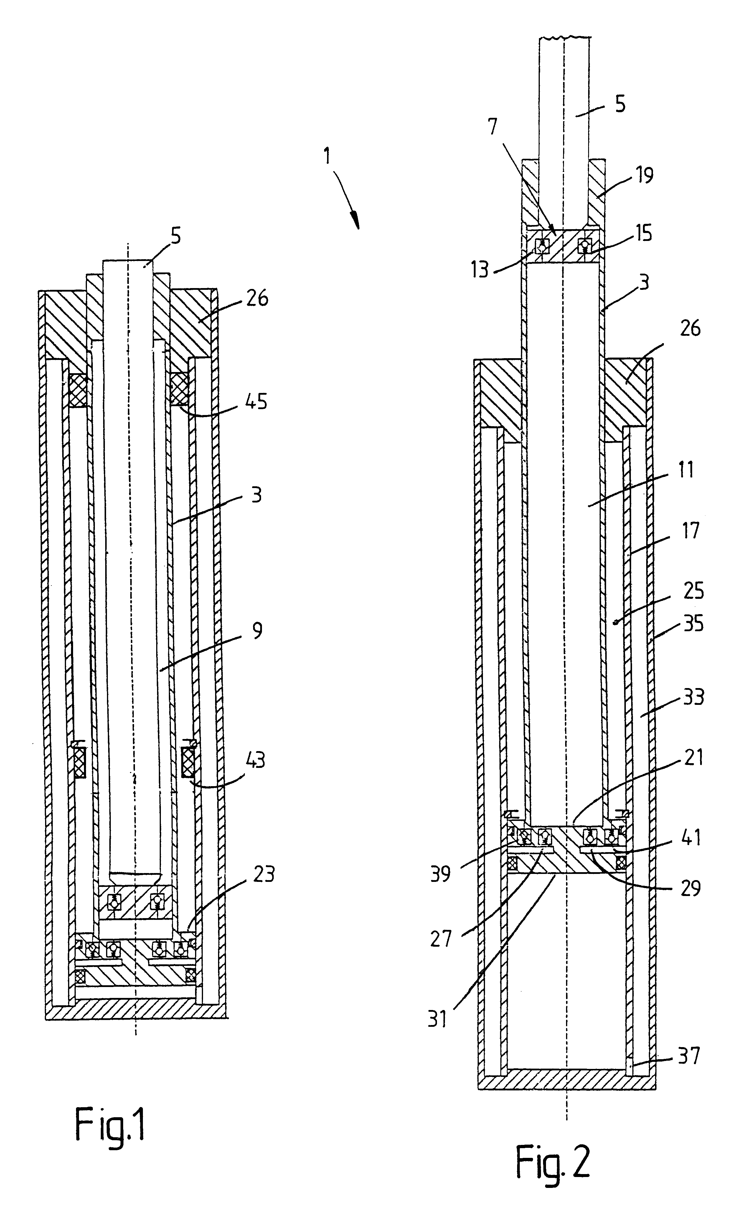
FIGS. 1 and 2 show a telescopic vibration damper 1, which has a pressure tube 3 in which a piston rod 5 with a piston 7 is arranged such that it can move axially, and subdivides the pressure tube into a working chamber 9 on the piston-rod side and a working chamber 11 remote from the piston rod. Apart from piston valves 13; 15 for the retraction direction and for the extension direction, the working chambers are separated hydraulically. The pressure tube 3 is axially movably guided in an intermediate tube 17, a piston-rod guide 19 for the piston rod being firmly connected to the pressure tube. FIGS. 1 and 2 are basic sketches, so that for reasons of clarity the detailed representation of the piston-rod guide with sealing elements and so on has been dispensed with.
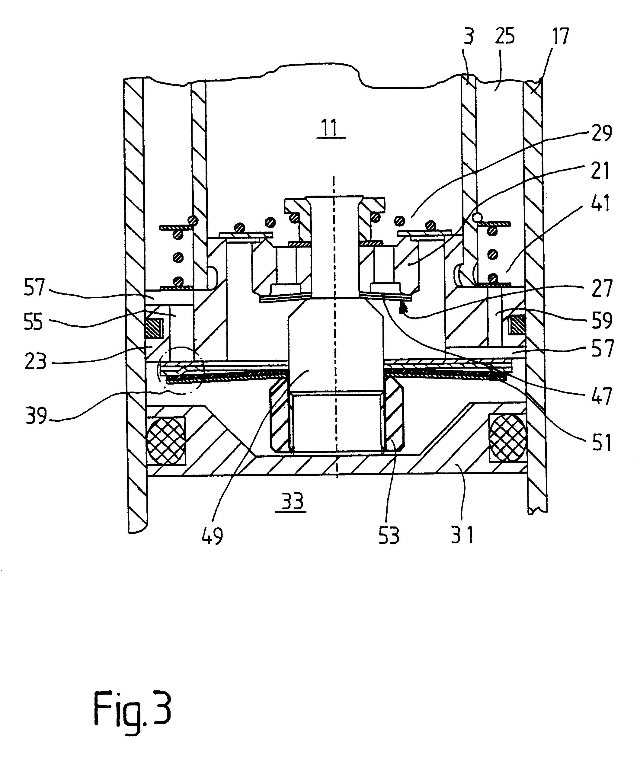
Fixed at the end of the pressure tube is a base 21, which has a piston section 23 located radially outside the pressure tube 3 and guided in the intermediate tube 17. The intermediate tube, the pressure tube and the piston ...
PUM
 Abstract
Description
Claims
Application Information