Connective structure for coupling printed circuit boards

a printed circuit board and connector technology, applied in the direction of coupling device connections, fixed connections, coupling device details, etc., can solve the problems of short connectors, affecting the visual inspection of relative position, and failing to resolve the prizing distortion of connectors

Inactive Publication Date: 2003-09-16
JST MFG CO LTD
View PDF4 Cites 20 Cited by
  • Summary
  • Abstract
  • Description
  • Claims
  • Application Information

AI Technical Summary

Benefits of technology

Preferably, a basal end of each positioning pin may protrude down from a bottom of the female connector housing so as to serve as a further positioning pin for precisely dispose the male connector relative to the second circuit board.

Problems solved by technology

This operation has often or sometimes caused a certain `prizing`or distortion in the one connector 3 relative to the other 4, thereby resulting in their defective fitting engagement.
Such shorter connectors have rendered difficult the visual check of their relative position, even if one circuit board 1 would be inclined as shown In FIG. 13(b).
Such a connective structure improved to more surely couple two printed circuit boards facing one another has however failed to resolve the `prizing` distortion of connectors.
The mating male and female connectors may accidentally take incorrect positions relative to each other, causing mutual collision of their housings.
Consequently, serious cracks are likely to be produced in the soldered portions to thereby fail to establish a reliable electric connection.

Method used


Image

  • Connective structure for coupling printed circuit boards
  • Connective structure for coupling printed circuit boards
  • Connective structure for coupling printed circuit boards

Examples


Embodiment Construction

Now some embodiments of the present invention will be described referring to the drawings.

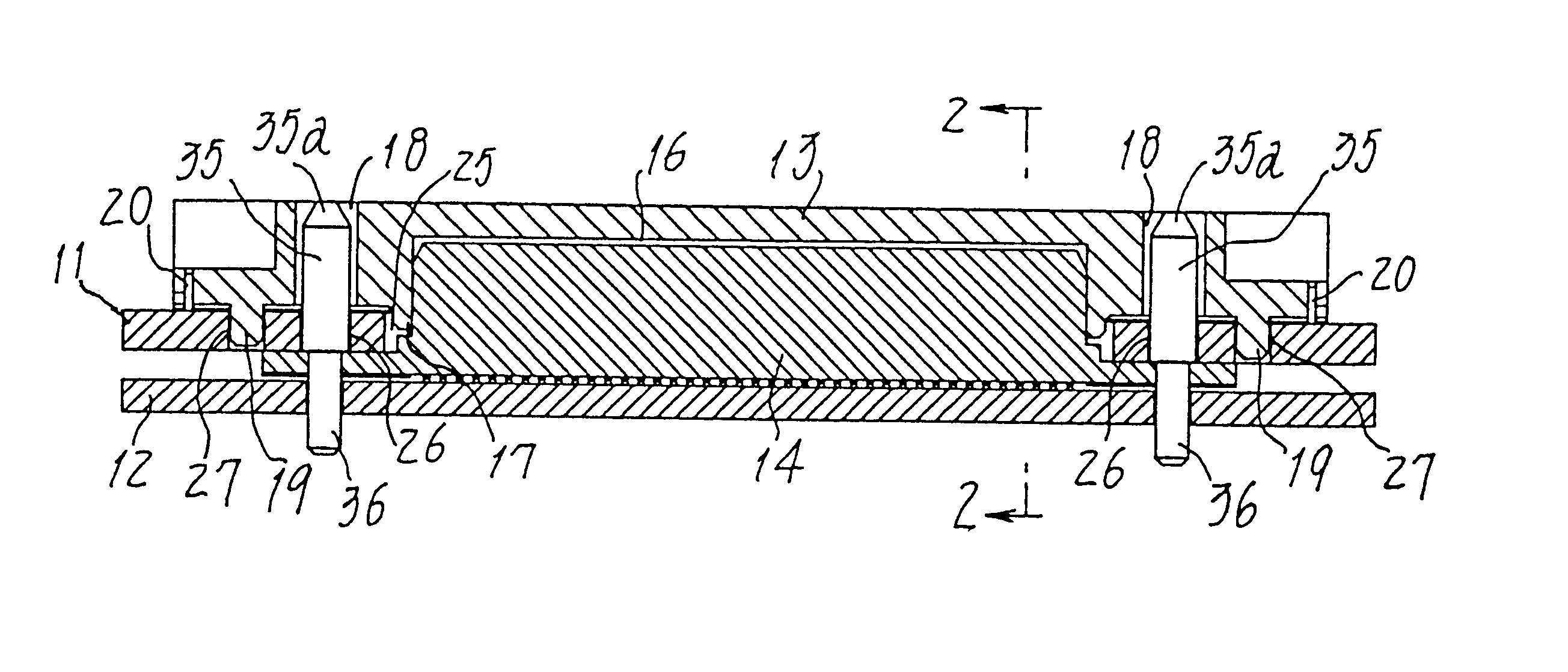
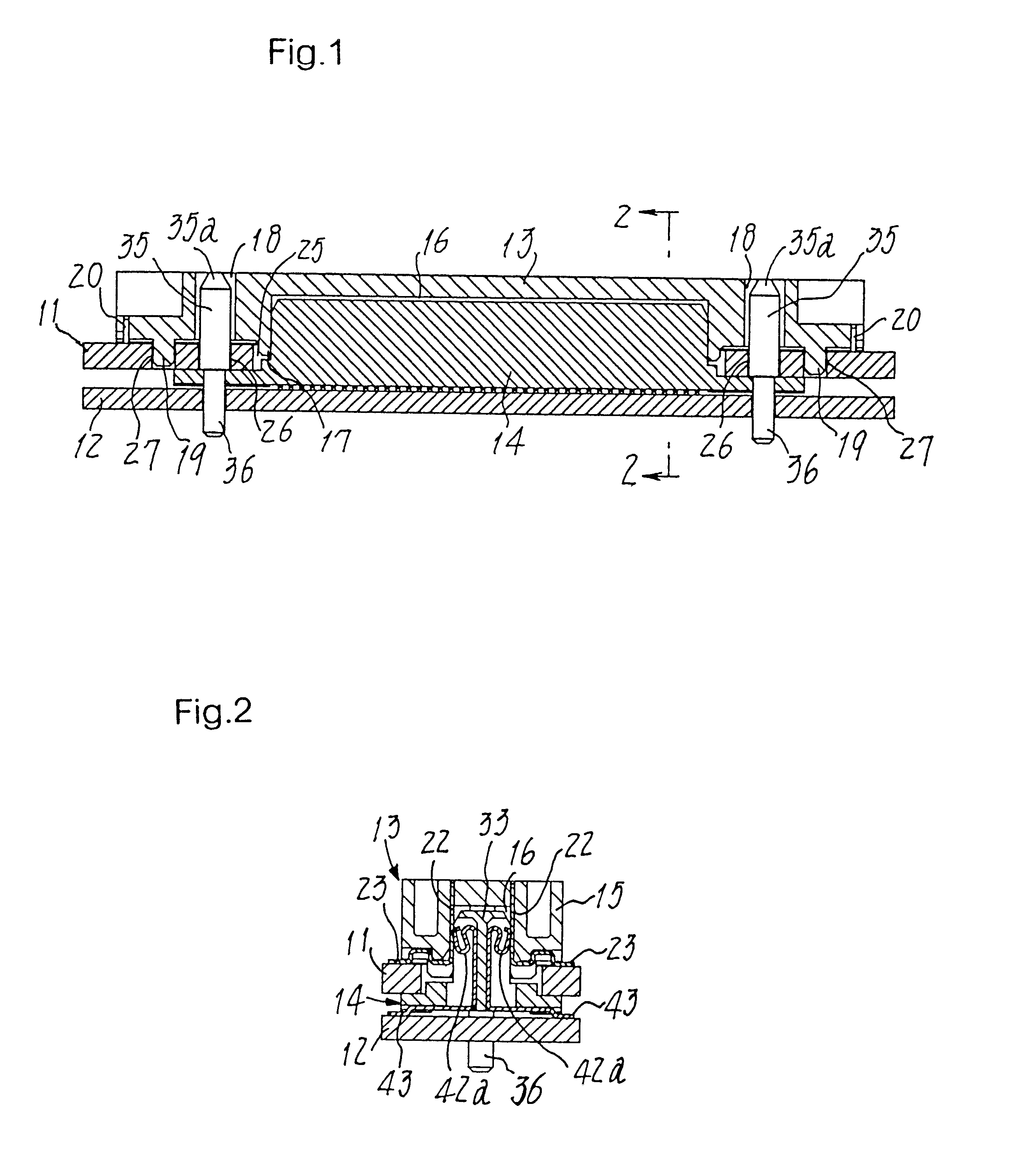
FIGS. 1 and 2 show a connective structure provided herein to couple two printed circuit boards 11 and 12 facing one another in a vertical direction. A female connector 13 surface-mounted on one of the circuit boards 11 is to be fitted on a male connector 14 also surface-mounted on the other board 12, so as to establish electric connection between these printed circuit boards.

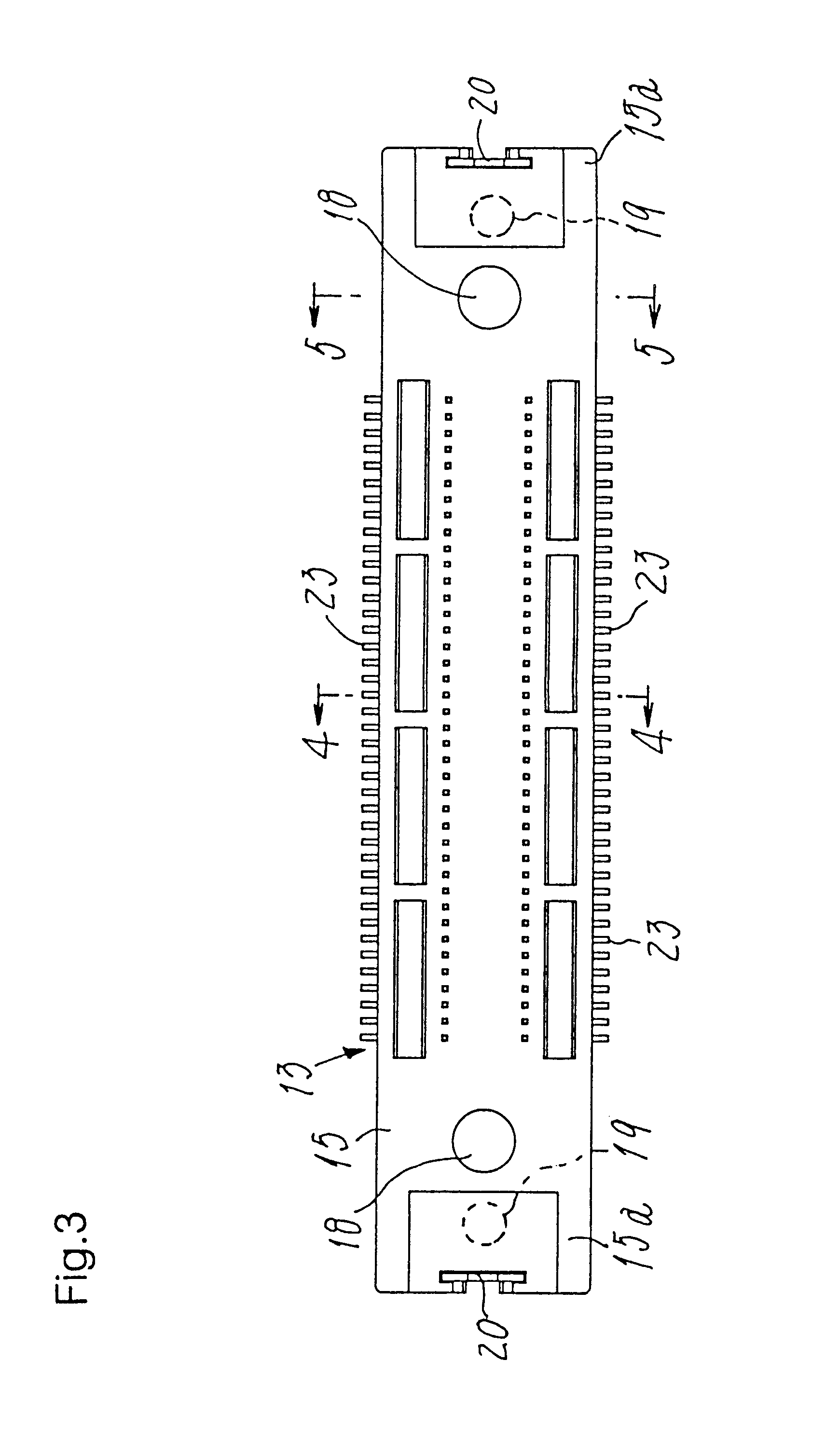
As seen in FIGS. 3 to 7, the female connector 13 comprises an insulated housing 15 and a plurality of first contacts 21 fixed therein. A cavity 16 having an open bottom and formed in the housing defines the latter to be a kind of elongate parallelepiped box. A rim 17 present in the lower face of housing 15 surrounds the open bottom of the cavity 16, and opposite end regions of said housing have guide holes 18 for loose reception of positioning pins 35. These pins protrude from the male connector 14, in a fashion as will be ...


PUM


Abstract

A connective structure for coupling a first and second printed circuit boards (11,12) facing one another is composed of a female connector (13) surface-mounted on the first printed board (11) and a male connector (14) also surface-mounted on the second board (12) so as to fit on the female connector (13). The male connector has a housing (41) and positioning pins (35) extending from opposite lateral ends of the housing towards the first printed circuit board, and each positioning pin has a free end protruding beyond the housing top. Positioning openings (26) are formed in the first circuit board so that the pins (35) are inserted in them to couple the female and male connectors (13,14) at their positions correct and accurate relative to each other to establish a reliable electric connection, such that the connective portions are protected from distortedly fitting one in another even if distance between the circuit boards (11,12) is reduced.

Description

1. Field of the InventionThe present invention relates to a connective structure for coupling two printed circuit boards facing one another.2. Prior ArtIn order to connect two mating printed circuit boards 1 and 2 together, a female connector 3 mounted on one of the circuit boards (hereinafter referred to often as `first`circuit board) 1 has been fitted on a male connector 4 mounted on the other circuit board (viz., `second` circuit board) 2 in a `lug-into-recess` manner shown in FIG. 13(a). In such a case, one of the first and second circuit boards 1 or 2 has to be inclined for visually checking the correct positions of male and female connectors 3 and 4 snapping into place. This operation has often or sometimes caused a certain `prizing`or distortion in the one connector 3 relative to the other 4, thereby resulting in their defective fitting engagement.In spite of this problem, it has recently been required to minimize the stacking distance between those printed circuit boards 1 a...

Claims


Application Information

Patent Timeline
Patent Type & Authority Patents(United States)
IPC IPC(8): H01R13/629H01R13/64H05K1/02H05K1/14
CPCH01R13/629H01R12/716H01R12/57H01R12/71
Inventor KIHIRA, SATORUHARASAWA, MASAAKITAGUCHI, HIROYUKI
Owner JST MFG CO LTD
Why Eureka
Try Eureka