Timing verification method employing dynamic abstraction in core/shell partitioning

a dynamic abstraction and core/shell partitioning technology, applied in computer aided design, program control, instruments, etc., can solve the problems of insufficient data, design will not work, and sequential timing optimization will be required more aggressively

Inactive Publication Date: 2003-09-16
CADENCE DESIGN SYST INC
View PDF3 Cites 34 Cited by
  • Summary
  • Abstract
  • Description
  • Claims
  • Application Information

AI Technical Summary

Problems solved by technology

Traditional techniques that consider one combinational block at a time in a sequential circuit can no longer suffice, and more aggressive sequential timing optimization will be required.
The data has to be there when the clock signal arrives, otherwise it isn't good data.
If the total delay through the combinational components is greater than the clock period, then the design will not work.
If one were to verify the timing of an entire design, the required memory may be more than the analysis memory available and in addition the CPU time for the verifier would be so long as to be unacceptable.

Method used


Image

  • Timing verification method employing dynamic abstraction in core/shell partitioning
  • Timing verification method employing dynamic abstraction in core/shell partitioning

Examples


Embodiment Construction

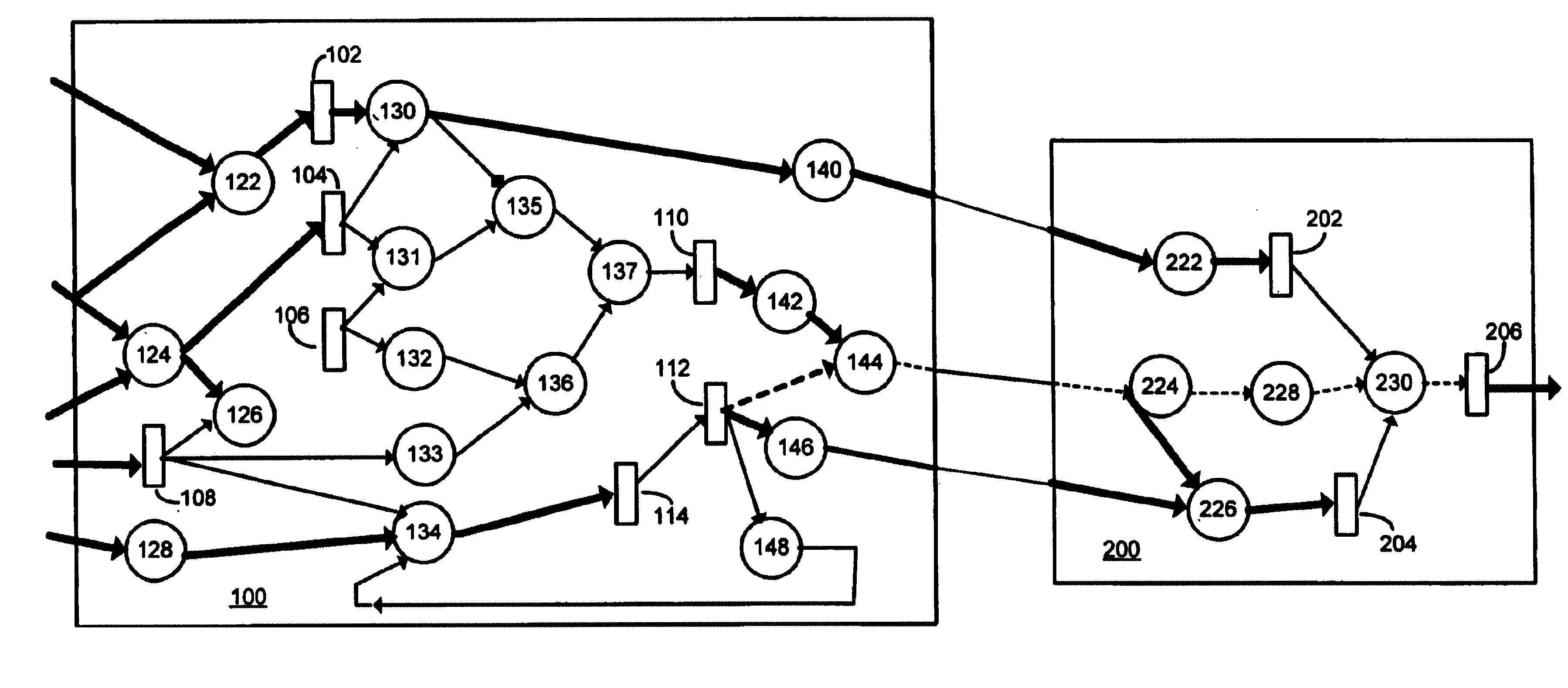
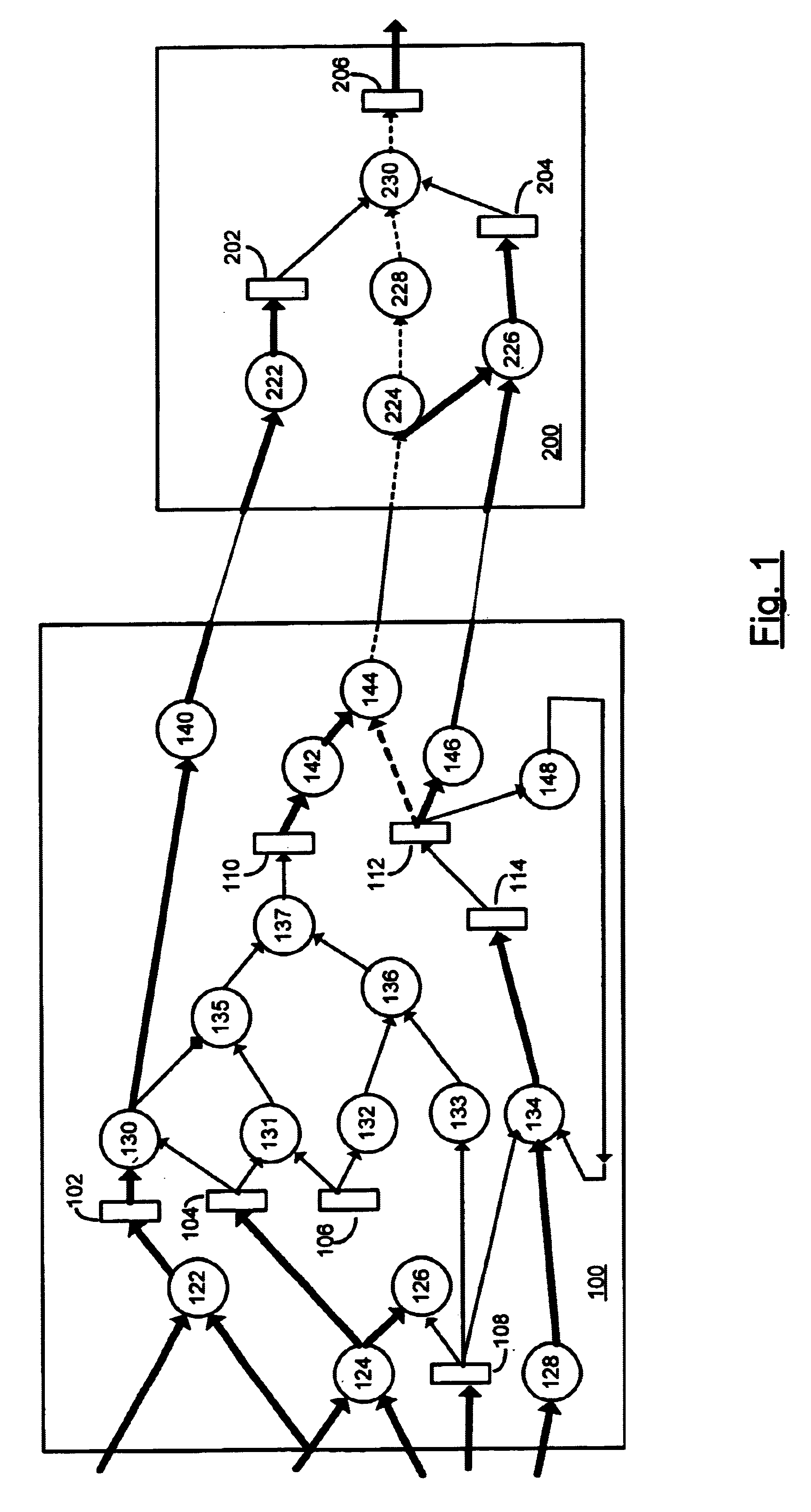
The invention is based on the division of an entire chip design into a plurality of individual blocks and then division of each block into a core and shell structure.

There are two parts to the invention. The first part follows from the realization that the logic elements within each physical block can be partitioned into two sets: those that participate in global timing constraints and those that do not. This yields a partition of each physical block into a core (elements limited to interacting with local timing constraints) and shell (elements related to global timing constraints) as shown in the accompanying FIG. 1.

The decomposition of the chip into global and local timing constraints is achieved using the notions of Core Paths and Shell Paths. For the purposes of this disclosure, a tri-state gate is treated as to a combinational logic gate. The term memory element refers to a flip-flop, level-sensitive latch or RAM / ROM element. The input of a memory element includes both the cloc...


PUM


Abstract

A method for timing verification of very large scale integrated circuits reduces required CPU speed and memory usage. The method involves steps including partitioning the circuit into a plurality of blocks and then partitioning the verification between shell path components and core path components. Timing verification is then conducted for only shell path components while core path components are abstracted or ignored. Finally, timing verification for core path components in each block completes the process for the entire design.

Description

1. Field of the InventionThe present invention relates generally to large VLSI circuit designs and more particularly to computer-aided timing analysis of sequential circuits.2. Background ArtCMOS Technology has made massive strides over the last two decades and is now the dominant choice for large VLSI designs. Recent projections on changes in technology have shown that great changes are required in design methodologies of the future to keep pace. Specifically, due to increases in design complexity, it will be essential for designers to place an even greater reliance on computer-aided design (CAD) tools to ensure the required increase in productivity. With timing optimization becoming one of the all-important factors as clock frequencies are forced upwards, CAD strategies for timing optimization are becoming essential. Traditional techniques that consider one combinational block at a time in a sequential circuit can no longer suffice, and more aggressive sequential timing optimizati...

Claims


Application Information

Patent Timeline
Patent Type & Authority Patents(United States)
IPC IPC(8): G06F17/50
CPCG06F17/5031G06F30/3312
Inventor GINETTI, ARNOLDHAHN, MARK STEVENKRIPLANI, HARISHAWAD, NASER
Owner CADENCE DESIGN SYST INC
Why Eureka
Try Eureka