Multi-positional paint tray

a paint tray and multi-position technology, applied in the field of paint trays, can solve the problems of difficult user to fix the paint tray in a vertically disposed position, the paint trays are notoriously unstable, and the use of standard paint trays on a stepladder is generally regarded as unsa

Inactive Publication Date: 2003-09-23
ROSA WALLACE B
View PDF18 Cites 72 Cited by
  • Summary
  • Abstract
  • Description
  • Claims
  • Application Information

AI Technical Summary

Benefits of technology

which will become apparent are met by a one-piece, large volume paint tray that can be used in a horizontal, as well as vertical, position to apply paint with a roller. Formed along the distal end of the paint tray is a partially enclosed basin that includes upward extending side walls, an end wall, and a top wall that extends to cover the basin. The corners between the end wall and the basin are curved thereby eliminating dead spaces so that a standard roller may pick up any paint located therein.
Formed on the proximal end of the paint tray is a pair of legs designed to elevate the proximal end so that the inclined surface is inclined when the paint tray is disposed horizontally. The shape of the legs and the overall length of the paint tray are sufficient so that the paint tray may be hung vertically when the legs rest on any rung of a standard ladder or stepladder, or may rest horizontally on the ladder shelf. In the preferred embodiment, the distal ends of the legs are sloped inward so that they engage the tread on a flat rung. Also attached to the distal ends is an optional extended lip structure designed to engage the surface of the step or rung. Also in the preferred embodiment, the legs are selectively attached to the paint tray so that the paint tray may be manufactured with the legs removed for compact shipping.
Aligned longitudinally and affixed to the proximal end of the paint tray is a short, rigid handle. The handle is securely affixed to the paint tray thereby preventing unwanted movement of the paint tray when the paint roller is rolled over the inclined surface or when the tray is maneuvered.

Problems solved by technology

It is also known that filled paint trays are notoriously unstable when filled with paint.
Because most users need at least one hand to climb a stepladder, using standard paint trays while on a stepladder is generally regarded as unsafe.
One serious drawback with the paint tray disclosed in U.S. Pat. No. 3,351,970 is that the handle is not fixed on the paint tray, making it difficult for the user to hold the paint tray in a fixed, vertically disposed position when the paint roller is dipped into the basin and rolled over the inclined surface.
The pivoting movement of the handle also increases the safety risk when the paint tray is used on a stepladder.
When moving up or down the stepladder, the user must reach underneath the body of the paint tray and grasp the handle and swing it upward, causing the user to push his body far out from the ladder in an unbalanced and unsafe position.
First, the drain board creates a large dead space that is filled with paint, greatly lowering the paint tray effective volume, when it is disposed in a horizontal position.
The body of the paint tray has sharp corners which also creates dead spaces.
The existence of dead spaces in a paint tray is troublesome because the paint partly dries and forms a skin which may be transferred to the wall surface and makes cleaning more difficult.
A second drawback with such paint trays is that the hook members must be extended around the rungs of a stepladder.
If the outer shape of the rungs and the hooks are not compatible, the paint tray cannot be safely attached to the rung.
Unfortunately, no means is provided for safely engaging the surface of the rungs.
A drawback with all paint trays in the prior art is that the raised contact surfaces formed on the inclined surface on the paint tray do not adequately remove or evenly distribute excessive paint from the roller.
Unfortunately, the raised bumps and transversely aligned chevrons commonly used in the prior art have both of these drawbacks.

Method used


Image

  • Multi-positional paint tray
  • Multi-positional paint tray
  • Multi-positional paint tray

Examples


Embodiment Construction

)

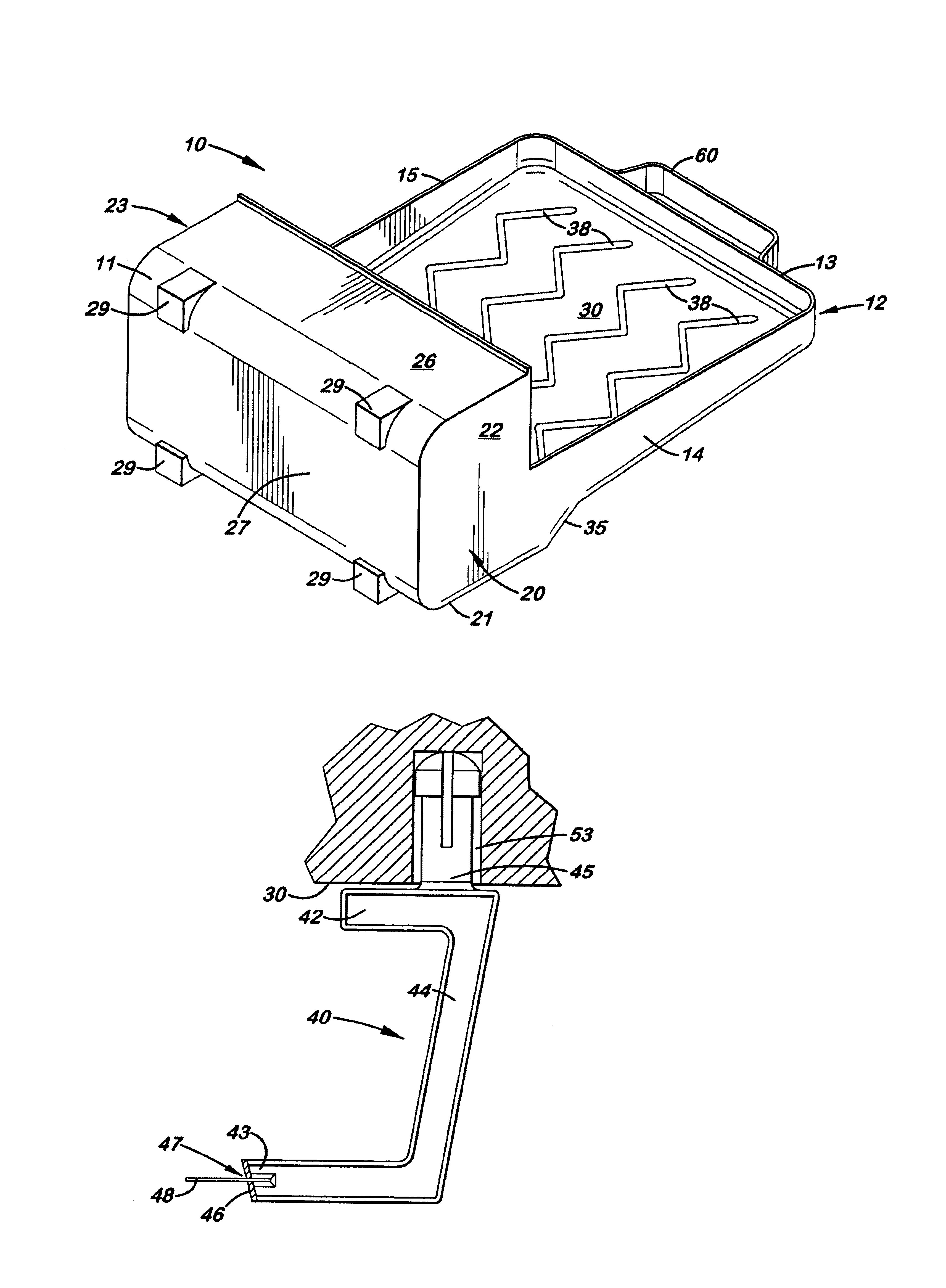
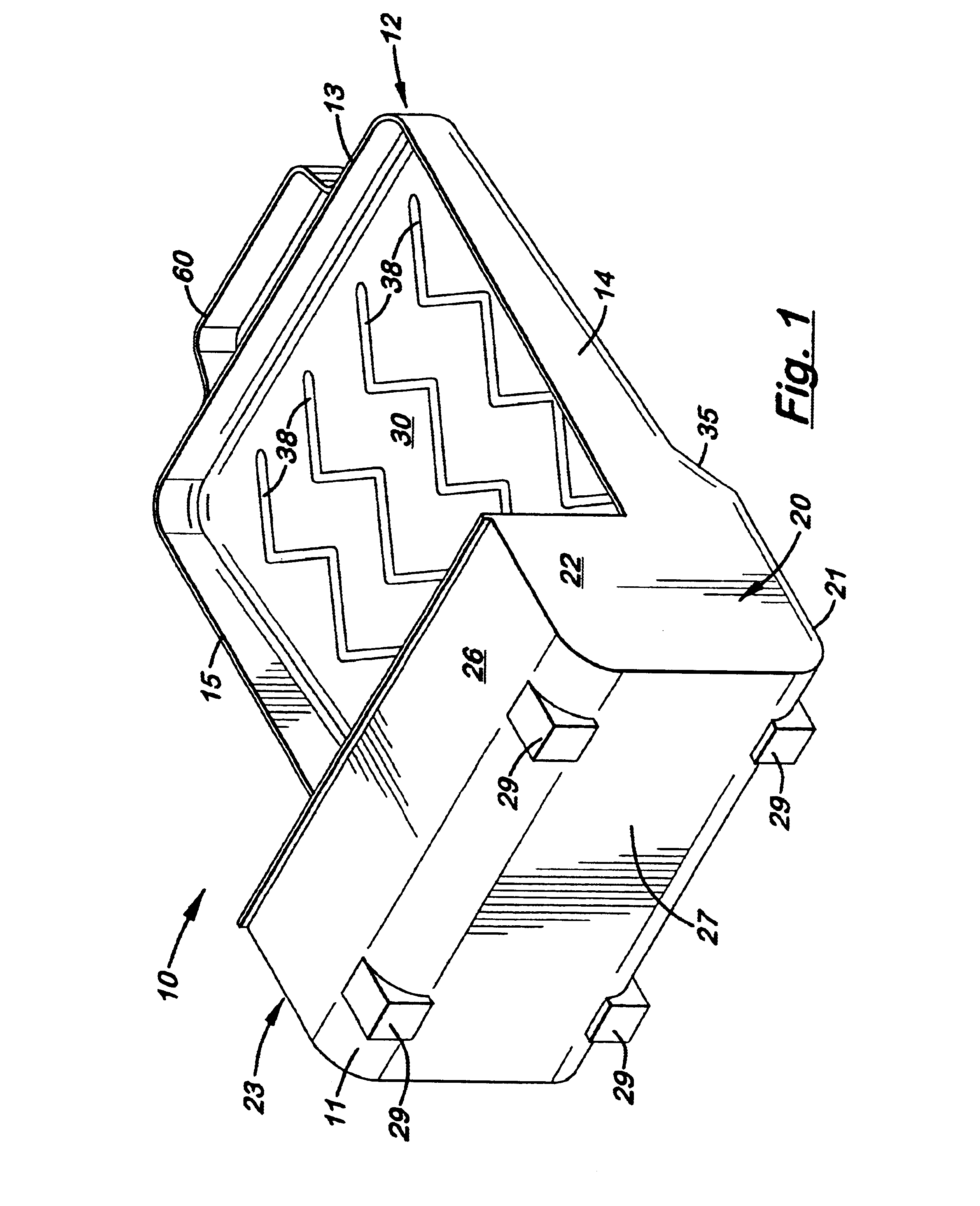
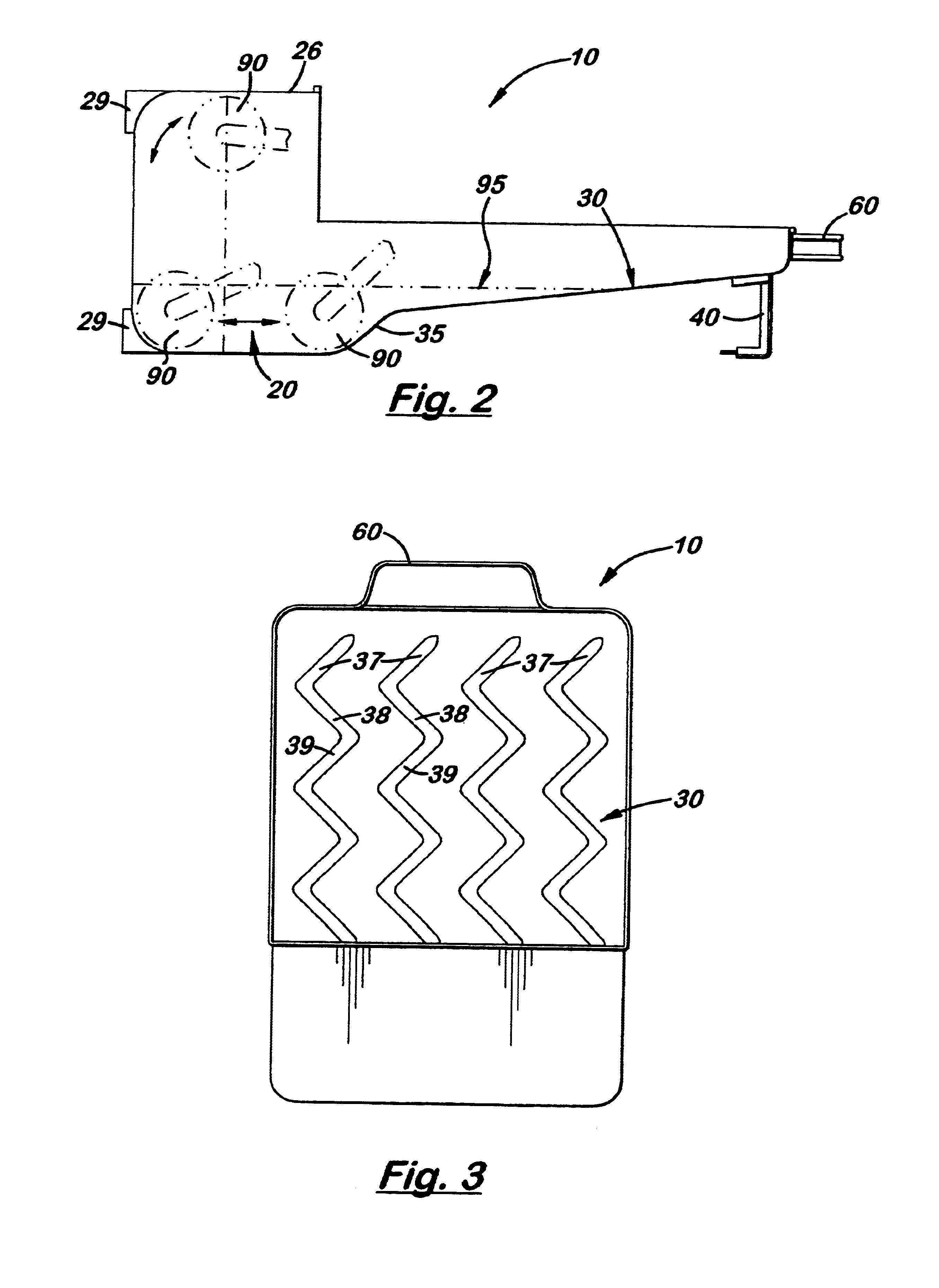
Referring to the accompanying FIGS. 1-9, shown and described is a paint tray 10 that can be used in both horizontal and vertical positions, to apply paint 95 from a roller 90. Formed along the distal end 11 of the tray 10 is a partially enclosed basin 20 that includes an end wall 27, two opposite sidewalls 22, 23, a bottom wall 21, and a top wall 26. The top wall 26 extends rearward, partially covering the bottom wall 21. The inside corners between the end wall 27 and the bottom and top walls 21, 26, respectively, are gently curved thereby enabling a roller 90 to continuously roll and pick up paint 95 located in the corners. Located on the distal end 11 of the tray 10, on the outside surface of the end wall 27, are feet projections 29 that enable of the tray 10 to stand upright in a vertical position on a support surface.

Formed inside the paint tray 10 is an inclined surface 30 designed to return excess paint 95 to the basin 20. As shown in FIG. 2, the bottom wall 21 on the basin 2...


PUM


Abstract

A paint tray that can be used in the vertical as well as horizontal position to hold paint for use with a roller. Formed longitudinally inside the tray is an inclined bottom surface designed to return excess paint to the basin when the paint tray is disposed horizontally. Formed on the inclined surfaces is a plurality of parallel raised contact surfaces that provides a directional contact surface used to remove excess paint from the roller and return the excess paint to the basin. The length of the inclined surface is sufficient to create freeboard for use in the vertical position without risk of spillage. The paint tray is equipped with a pair of legs attached to its distal end that allows the paint tray to rest vertically on the rung(s) of a ladder or step(s) of a stepladder, or horizontally on the ladder shelf as traditional paint trays. Aligned longitudinally on the distal end of the paint tray is a rigid handle for easy transport of the paint tray in the vertical position. Also aligned longitudinally on the proximal end of the paint tray are a plurality of feet that enable the paint tray to stand vertically on a support surface.

Description

1. Field of the InventionThis invention pertains to paint trays, and, more particularly, to paint trays used with paint rollers.2. Description of the Related ArtPaint trays are commonly used to apply paint to a surface using a paint roller. Typically, paint trays are an open pan-like structure with four upward extending side walls and an inclined bottom surface that recedes at one end to form a flat basin which is filled with a small amount of paint. Short legs are attached to the proximal end of the structure to elevate the proximal end of the bottom inclined surface relative to the basin so that paint deposited on the inclined surface automatically flows back to the basin when the tray is disposed in a horizontal position.It is widely known that when painting with a paint roller, the user must frequently refill the paint tray. Standard paint trays have a working volume of approximately one pint of paint that is sufficient to cover approximately fifty square feet or about six runni...

Claims


Application Information

Patent Timeline
Patent Type & Authority Patents(United States)
IPC IPC(8): B44D3/12B05C17/02
CPCB05C17/0245B44D3/126B44D3/128
Inventor ROSA, WALLACE B.
Owner ROSA WALLACE B
Why Eureka
Try Eureka