Lock construction having an electrically activated clutch mechanism and a transmission mechanism

a technology of electrical activation and clutch mechanism, which is applied in the direction of mechanical control devices, wing knobs, keyhole guards, etc., can solve the problems of difficulty in mass production, and achieve the effects of easy assembly, simple construction, and easy modification of orientation

Inactive Publication Date: 2003-09-23
TUNG LUNG METAL IND
View PDF11 Cites 53 Cited by
  • Summary
  • Abstract
  • Description
  • Claims
  • Application Information

AI Technical Summary

Benefits of technology

It is thus of a primary object of this invention to provide a lock construction to be used with a lock construction, that is of a simple construction and that can be easily assembled.
It is another object of this invention to provide a handle mechanism which orientation can be easily modified.

Problems solved by technology

The conventionally locks, particularly electronic locks, are mostly of very complicated constructions, such that they cannot be easily assembled, and cause difficulty in mass production.

Method used


Image

  • Lock construction having an electrically activated clutch mechanism and a transmission mechanism
  • Lock construction having an electrically activated clutch mechanism and a transmission mechanism
  • Lock construction having an electrically activated clutch mechanism and a transmission mechanism

Examples


Embodiment Construction

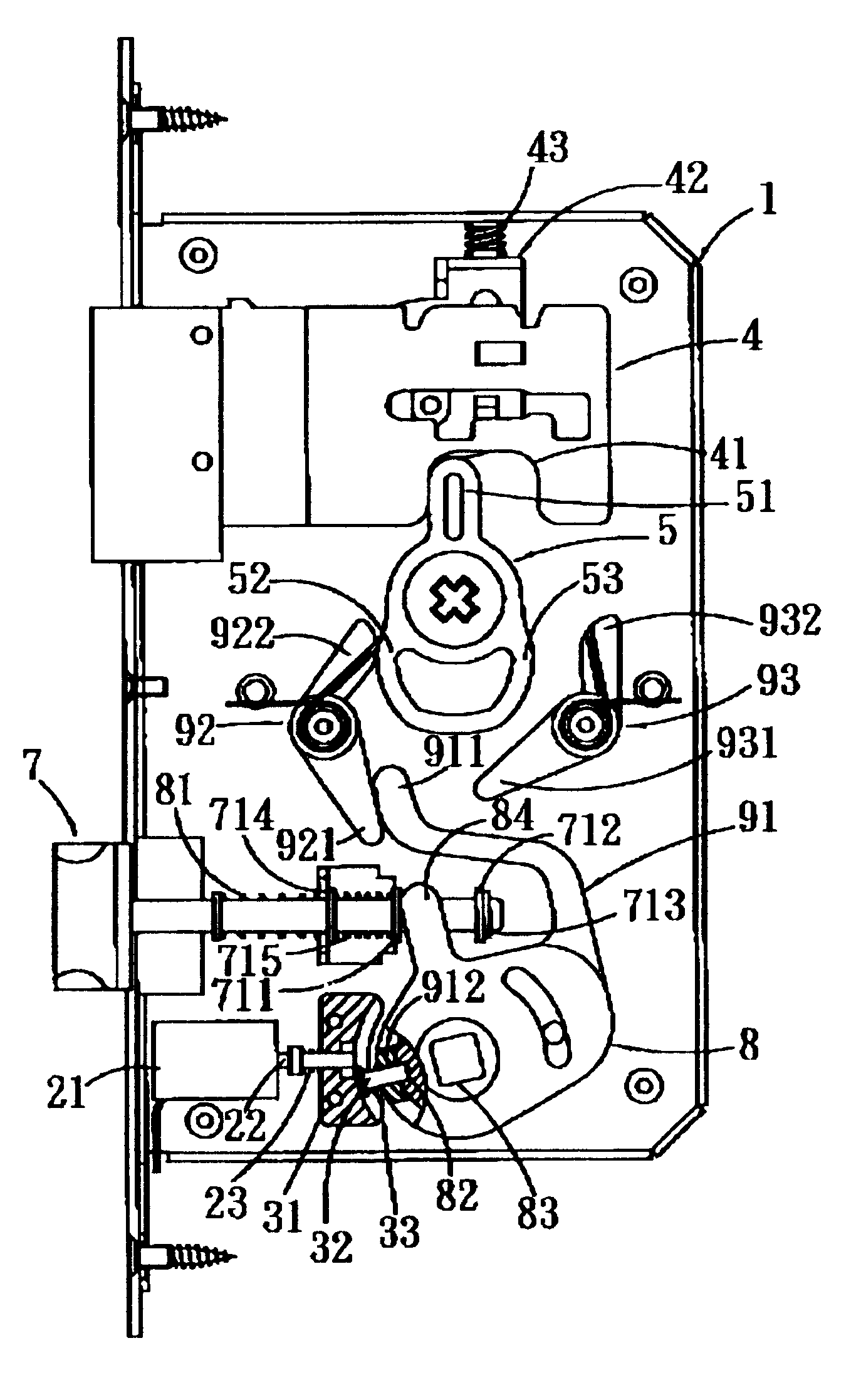
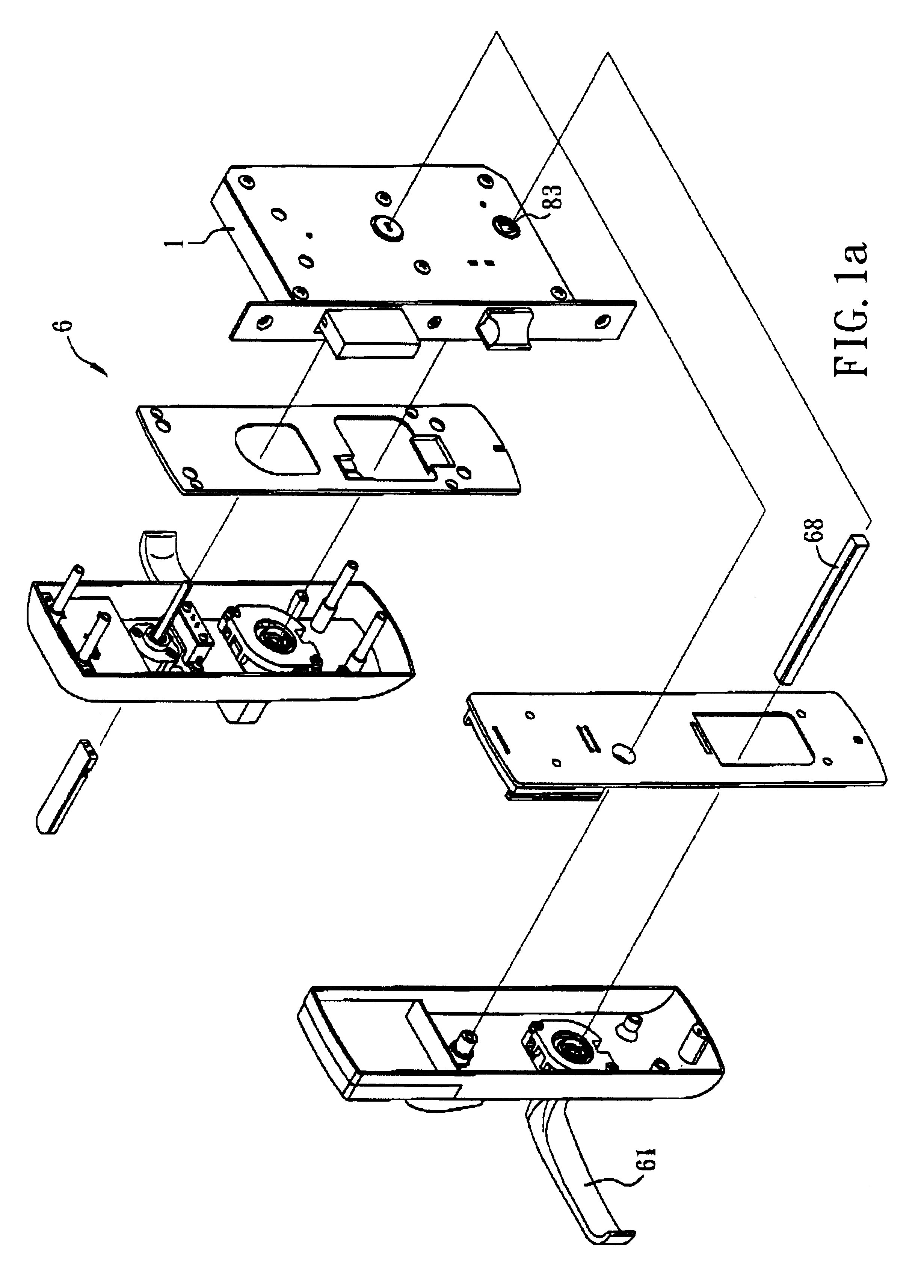
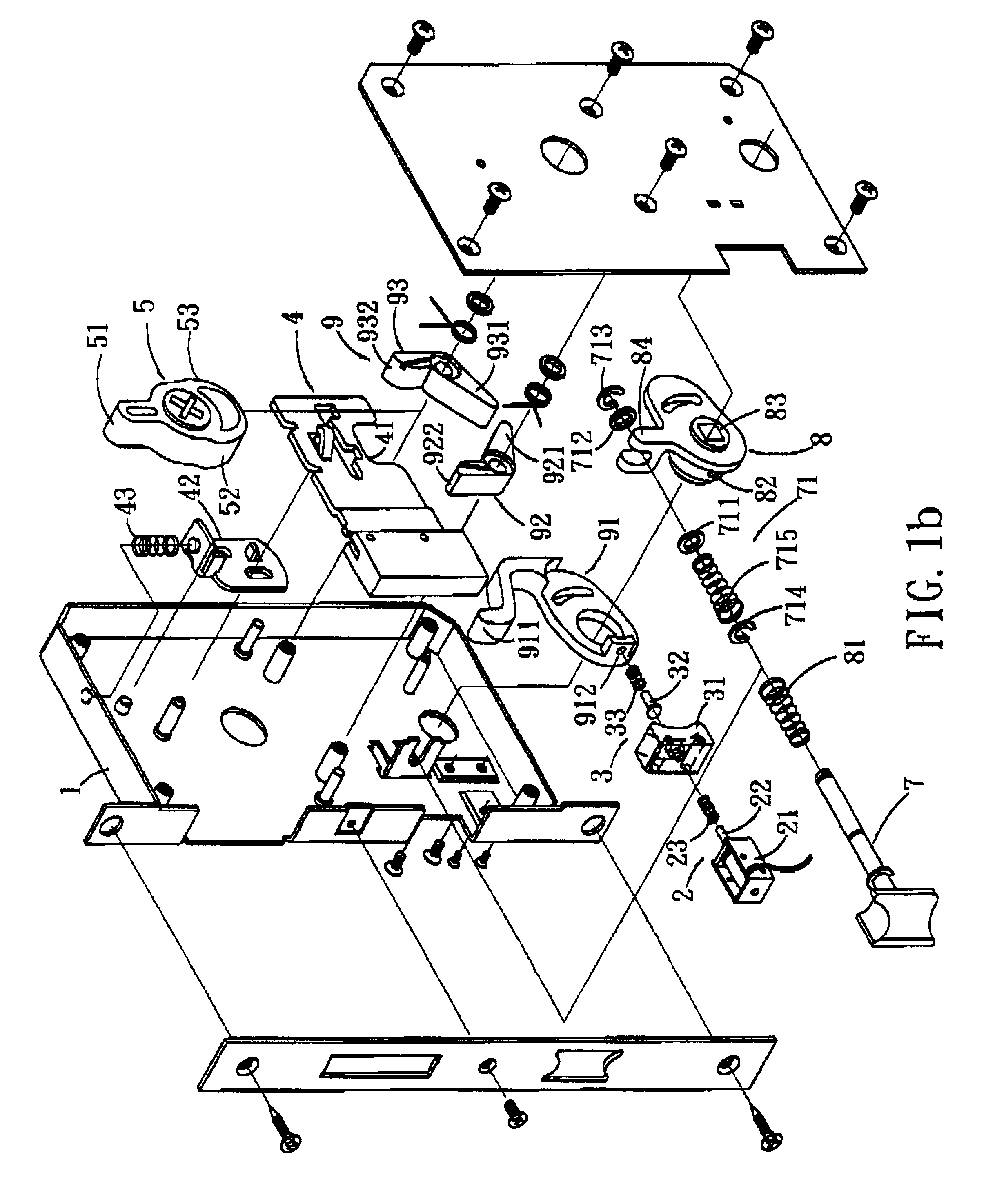
FIG. 1a illustrates the exploded, perspective view of the preferred embodiment embodying the lock construction of this invention. FIG. 1b is an illustrative view showing the details of an electronic latch used in this invention. As shown in FIGS. 1a and 1b, the lock construction of this invention comprises: a housing 1, an active driving mechanism 2, a clutch mechanism 3 to be activated by the active driving mechanism 2, a first latch 4, a stopping member 42 retaining the first latch 4 in a retracted or an extended position, a first latch-driving member 5 driving the first latch 4 and the stopping member 42, a second latch 7, a second latch-driving member 8 driving the second latch 7, a latch spring 81 normally urging the second latch 7 to an extended position and co-acting between the second latch 7 and the second latch-driving member 8, a transmission mechanism 9 to be activated by the second latch-driving member 8 to drive the first latch-driving member 5, and a handle mechanism ...


PUM


Abstract

This invention is related to a lock construction comprising: an active driving mechanism, a clutch mechanism, a first latch, a first latch-driving member, a second latch, a second latch-driving member, a latch spring, a transmission mechanism, and a handle mechanism. In one embodiment, the lock construction comprises a clutch mechanism that can be activated electrically to allow latching or unlatching of the door. In an alternative embodiment, the lock construction comprises a transmission mechanism that can drive two latches of the lock simultaneously to latch or unlatch the door.

Description

This invention provides a lock construction comprising: an active driving mechanism, a clutch mechanism, a first latch, a first latch-driving member, a second latch, a second latch-driving member, a latch spring, a transmission mechanism, and a handle mechanism. The handle mechanism includes a handle, a case, a coil spring, a retaining plate, a clip, and a coverlid. As such, the lock construction is of a simple construction, such that the lock can be mass-produced, and that the handle mechanism can be easily adjusted to a left- or a right-swing door.BACKGROUND OF INVENTIONThis invention is related to a lock construction, in particular to one that is of a simple structure, that can be mass produced, and that having a handle mechanism can be easily adjusted to be applied to a left- or a right-swing door.SUMMARY OF INVENTIONThe conventionally locks, particularly electronic locks, are mostly of very complicated constructions, such that they cannot be easily assembled, and cause difficul...

Claims


Application Information

Patent Timeline
Patent Type & Authority Patents(United States)
IPC IPC(8): E05B47/06E05B1/00
CPCE05B47/0692E05B47/0004E05B2001/0076Y10S292/27Y10T70/5496Y10T70/5805Y10T70/5416Y10T70/5226Y10T70/7062
Inventor CHIANG, WEI-LUNGHUNG, TSUNG-CHUNGCHEN, PO-YANGLIN, CHEN-MING
Owner TUNG LUNG METAL IND
Why Eureka
Try Eureka