Method of producing vibration-isolating bushing

a technology of vibration isolation and bushing, which is applied in the direction of manufacturing tools, forging presses, other domestic articles, etc., can solve the problems of deterioration in durability, significant weight increase, and cost increas

Inactive Publication Date: 2003-09-30
TOYO TIRE & RUBBER CO LTD
View PDF7 Cites 6 Cited by
  • Summary
  • Abstract
  • Description
  • Claims
  • Application Information

AI Technical Summary

Problems solved by technology

However, where such a thick-walled inner cylinder 101 is employed, the area of each of the edge surfaces 108 is enlarged, yet the problem is encountered that its weight is significantly increased.
In this case, however, because of the profiled shape of the inner cylinder 101, such a preformed material that is worked by forging, etc. is employed and hence a cost increase is entailed.
Furthermore, when the rubber elastomer 103 is molded by vulcanization, the free length of each of edge surfaces 110 of the rubber elastomer 103 cannot be sufficiently secured from the respect of mold releasing after molding, etc. and consequently, there is a problem of deterioration in durability.

Method used


Image

  • Method of producing vibration-isolating bushing
  • Method of producing vibration-isolating bushing
  • Method of producing vibration-isolating bushing

Examples


first embodiment

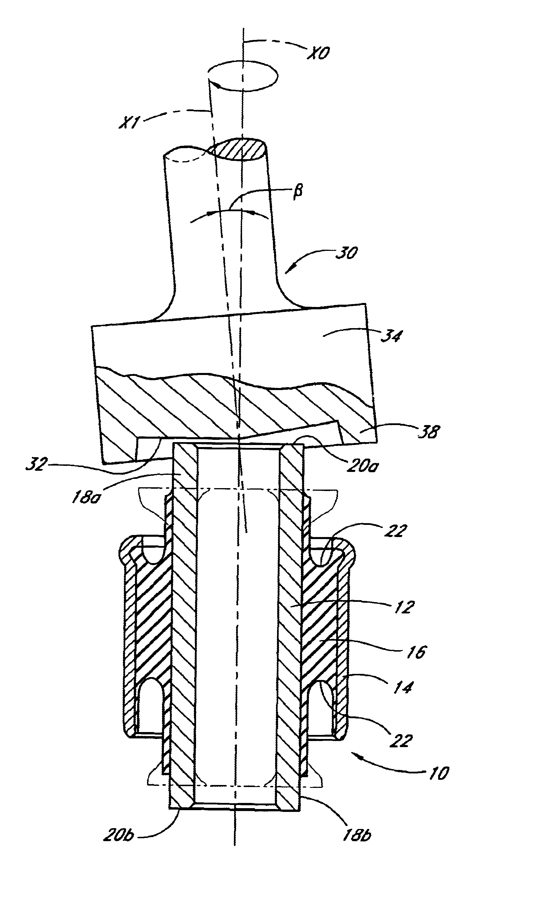
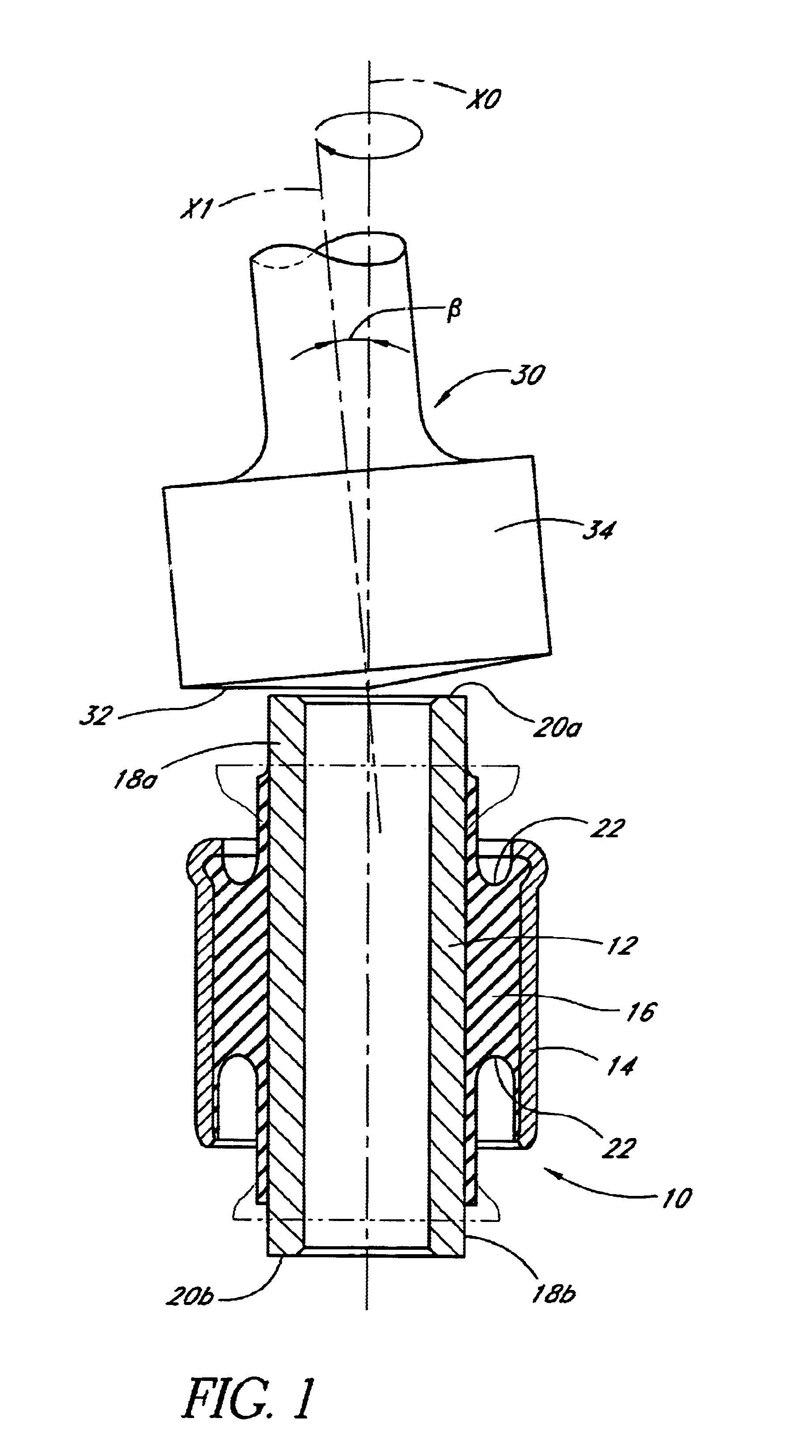
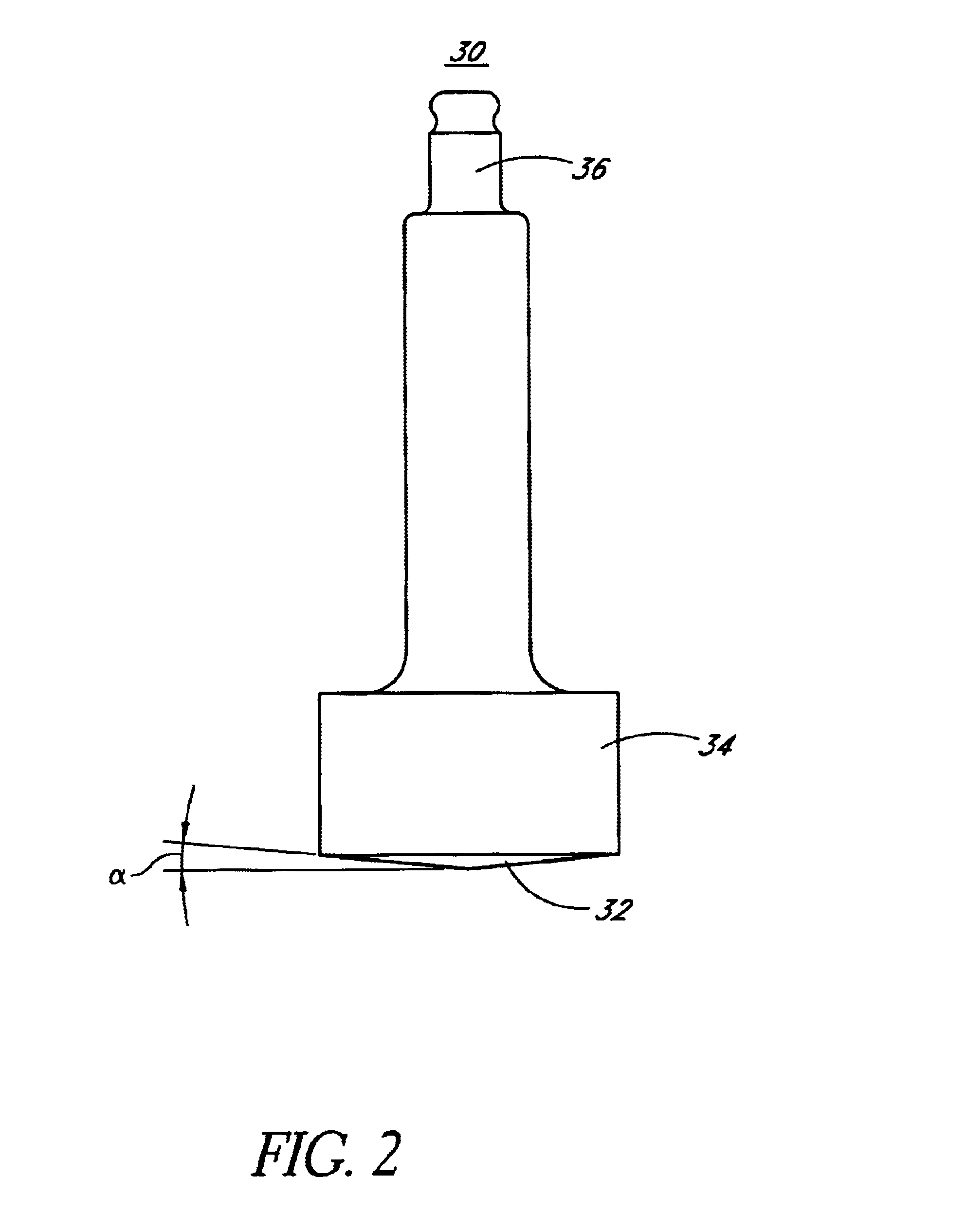
FIGS. 1 to 3 are concerned with this invention; FIG. 1 is a sectional view of a vibration-isolating bushing 10 upon upsetting working, FIG. 2 is an elevational view of an upsetting jig 30 used for the upsetting working, and FIG. 3 is a sectional view of the vibration-isolating bushing 10 thus obtained.

That is, the vibration-isolating bushing 10 is made up of an inner cylinder 12 and an outer cylinder 14 concentrically arranged in a spaced relation and made of a metal tube such as iron, steel, aluminum or alloy thereof, and a rubber elastomer 16 interposed between the inner and outer cylinders 12, 14 by vulcanization molding to bond integrally both cylinders. The rubber elastomer 16 is secured to an outer circumferential surface of the inner cylinder 12 and an inner circumferential surface of the outer cylinder 14 by vulcanization adhesion means. As shown in FIG. 3 the inner cylinder 12 is somewhat longer than the outer cylinder 14 and the rubber elastomer 16, and upset at both extre...

second embodiment

This second embodiment is different from the first embodiment in the shape of the upsetting jig 30 for working extremities of the inner cylinder 12. That is, in this embodiment, a constraint wall 38 for surrounding the whole outer peripheries of the extremities 18a, 18b of the inner cylinder 11 to be upset is disposed vertically in the peripheral portion of the top edge surface 32 assuming a nearly flat conical surface of the upsetting jig 30 so as to restrain the extremities 18a, 18b of the inner cylinder from being upset more than a required diameter.

As shown in FIG. 5, the constraint wall 38 is formed to project downwardly from the periphery of the top edge surface 32 of the columnar portion 34, namely forwardly in the pressing direction and its inside is formed to be in a nearly flat conical plane. The wall surface at the inner periphery side of the constraint wall 38 is tilted outwardly by a required angle .gamma., and the angle .gamma. is set to be nearly the same as the tilti...


PUM

PropertyMeasurementUnit
outer circumferenceaaaaaaaaaa
inner diameteraaaaaaaaaa
areaaaaaaaaaaa

Abstract

A method of producing a vibration-isolating bushing with which it is possible to secure a larger area of the edge surface of an inner cylinder than in the prior art method. In upsetting one extremity of the inner cylinder by cold plastic working, after a rubber elastomer is secured to the outer circumference of the inner cylinder by vulcanization molding, as a jig for pressing onto the edge surface of the inner cylinder, an upsetting jig whose top surface is flat is used and the top surface of the jig is pressed onto the edge surface of the inner cylinder while causing the jig to gyrate on a conical orbit centering the axis of the inner cylinder, whereby the outside diameter only of the extremity is enlarged while suppressing the enlarging of the inside diameter.

Description

1. Field of the InventionThis invention relates to a method of producing a vibration-isolating bushing which is mainly used by being assembled into an automobile suspsension system or the like.2. Description of Related ArtIn an automobile suspesnsion system, a cylindrical vibration-isolating bushing is generally used at a coupling part between the vehicle body and the suspension, namely the coupling part between a lower arm or other arm for supporting wheels and a vehicle body side member such as a frame with a view to vibration damping and shock absorbing. The cylindrical vibration-isolating bushing can also be used for an engine mount supporting or bearing the engine in a vibration-proof fashion.A conventional vibration-isolating bushing is, for example, known in the art as shown in FIG. 8, wherein the bushing 100 is made up of an inner cylinder 101 and an outer cylinder 102 both made of metal and disposed concentrically, and a rubber elastomer 103 interposed between the both. Whe...

Claims


Application Information

Patent Timeline
Patent Type & Authority Patents(United States)
IPC IPC(8): B21K21/12B21K21/00B21J9/02B21J9/00F16F1/38B21D19/00B21J5/08B21K1/26
CPCB21J9/025B21K21/12F16F1/3842Y10T29/49668F16F2226/04
Inventor KAWADA, MICHIHIROTAKAHASHI, HIROAKITADANO, HIDEO
Owner TOYO TIRE & RUBBER CO LTD
Why Eureka
Try Eureka