

Apparatus for manufacturing electron source, method for manufacturing electron source, and method for manufacturing image-forming apparatus
a technology of electron source and manufacturing method, which is applied in the manufacture of electrode systems, lighting and heating apparatus, and tube/lamp factory adjustmen
- Summary
- Abstract
- Description
- Claims
- Application Information
AI Technical Summary
Problems solved by technology
Method used
Image

Examples
second embodiment
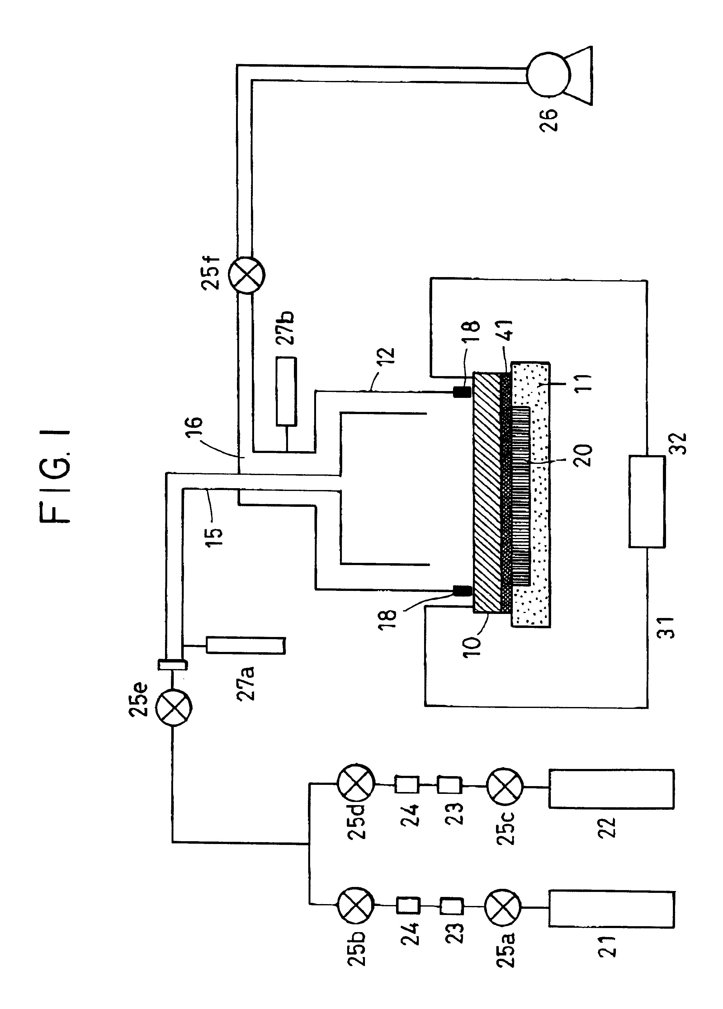
In this embodiment, an apparatus similar to that shown in FIG. 1, except that a diffuser panel 19 is disposed in a vacuum container 12, is used A forming process is performed to form a gap G in a conductive film shown in FIG. 7 and an activation process is performed in the same manner as in the first embodiment, and thus an electron source is manufactured.
FIG. 3 is a sectional view showing the structure of an apparatus for manufacturing an electron source in the second embodiment. The diffuser panel 19 provided with openings 33 is disposed above an electron source substrate 10. With respect to the openings 33 of the diffuser panel 19, an opening in the center (at the intersection point between the extension from the center of the gas inlet and the diffuser panel) is circular with a diameter of 1 mm, and openings are placed in a concentric shape, radially with a spacing of 5 mm and circumferentially with a spacing of 5.degree. so as to satisfy the equation below. The distance from th...
third embodiment
In this embodiment, an electron source is manufactured in the same manner as in the second embodiment except the activation process is performed on two lines simultaneously among ten lines, instead of one by one.
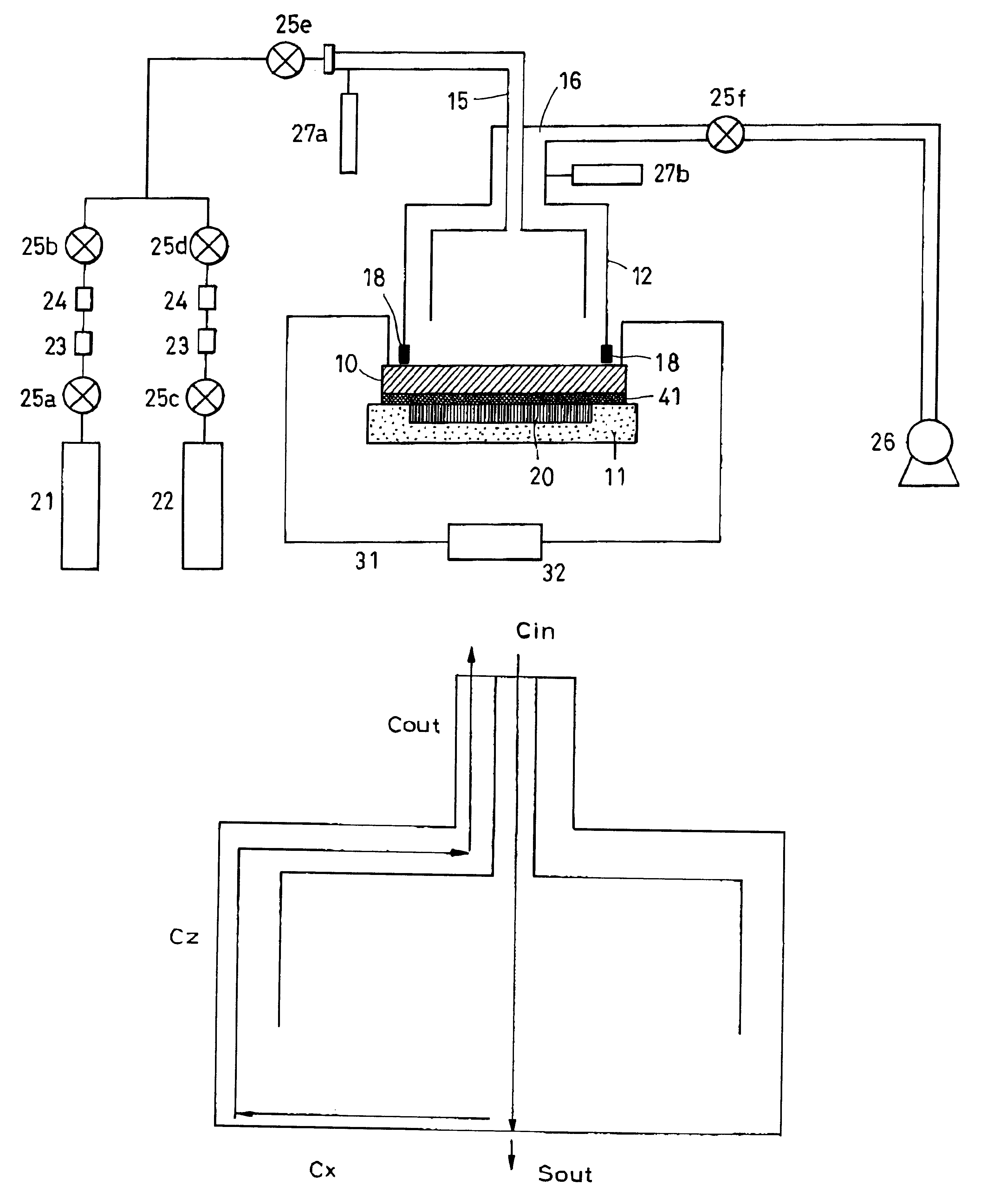
Following the forming process, the activation process is performed. The valves 25a and 25b for supplying gas and the valve 25e at the gas inlet 15 side shown in FIG. 3 are opened and an organic substance gas 21 is introduced into the vacuum container 12. Benzonitrile is used as the organic substance gas 21, and the degree of opening of the valve 25e is adjusted while monitoring the pressure measured by the vacuum gauge 27a at the gas inlet side so that the pressure is 4.times.10.sup.-4 Pa (3.times.10.sup.-6 Torr).
In this embodiment, the introduction and exhaust of the activation gas are performed under the conditions described below so that the amount of the reduction in the partial pressure and the range of partial pressure distribution during activation are limited to 20% ...
fourth embodiment
In this embodiment, an electron source is manufactured in the same manner as that in the third embodiment apart from the fact that the activation process is performed simultaneously on two lines which are apart from each other by the total number of lines / 2.
Following the forming process, the activation process is performed. The valves 25a and 25b for supplying gas and the valve 25e at the gas inlet 15 side shown in FIG. 3 are opened and an organic substance gas 21 is introduced into the vacuum container 12. Benzonitrile is used as the organic substance gas 21, and the degree of opening of the valve 25e is adjusted while monitoring the pressure measured by the vacuum gauge 27a at the gas inlet side so that the pressure is 4.times.10.sup.-4 Pa (3.times.10.sup.-6 Torr).
In this embodiment, the introduction and exhaust of the activation gas are performed under the conditions described below so that the amount of the reduction in the partial pressure and the range of partial pressure dist...
PUM
 Abstract
Description
Claims
Application Information