Gas sensing element incorporated in a gas sensor for an internal combustion engine

a gas sensor and gas sensor technology, applied in the field of gas sensing elements, can solve the problems of deteriorating the sensing properties of the gas sensing element, the prior art cannot bring satisfactory effects against poisonous substances of gas phase, etc., and achieve the effect of stable sensor outpu

Inactive Publication Date: 2003-10-14
DENSO CORP
View PDF12 Cites 4 Cited by
  • Summary
  • Abstract
  • Description
  • Claims
  • Application Information

AI Technical Summary

Benefits of technology

As described above, the present invention can provide a gas sensing element which is capable of preventing poisonous gaseous substances, such as Si components, from reaching the measured gas sensing electrode, and accordingly capable of preventing the measured gas sensing electrode from being covered by the poisonous substances of gas phase, and therefore capable of maintaining a stable sensor output for a long time.

Problems solved by technology

However, the above-described prior art cannot bring satisfactory effects against poisonous substances of gas phase, such as Si components, contained in the seal member or the like of the internal combustion engine.
As a result, Si components deteriorate the sensing properties of the gas sensing element.

Method used


Image

  • Gas sensing element incorporated in a gas sensor for an internal combustion engine
  • Gas sensing element incorporated in a gas sensor for an internal combustion engine
  • Gas sensing element incorporated in a gas sensor for an internal combustion engine

Examples


first embodiment

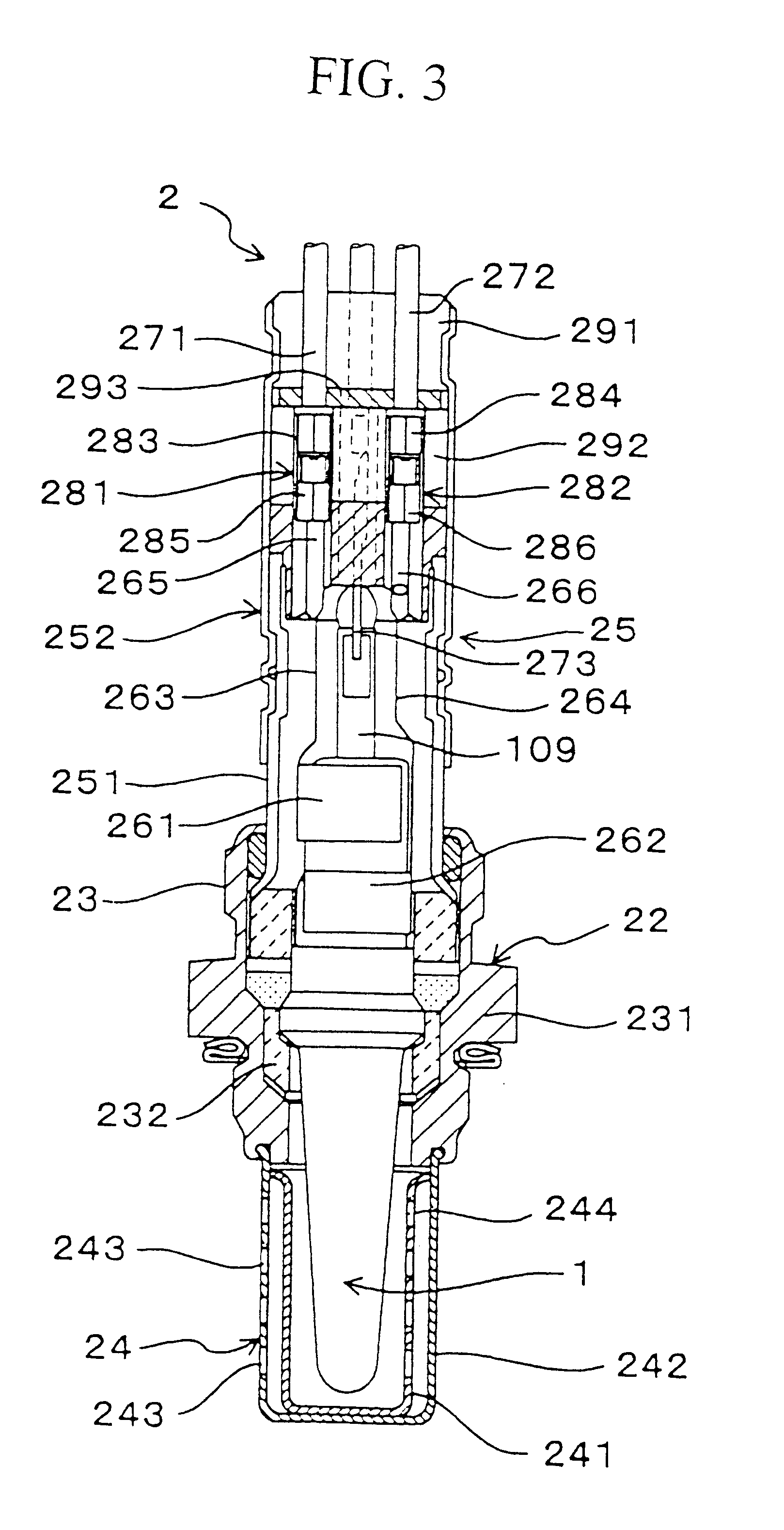
Hereinafter, a gas sensing element according to a preferred embodiment of the present invention will be explained with reference to FIGS. 1 to 3.

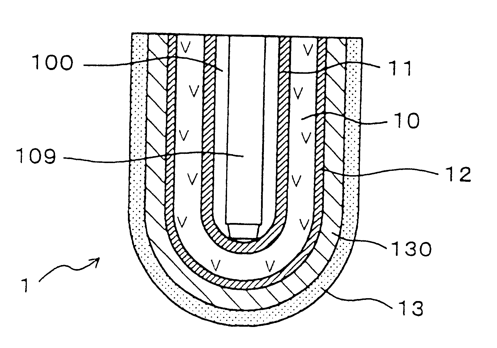
As shown in FIG. 1, the gas sensing element 1 of this embodiment comprises a cup-shaped solid electrolytic body 10 with one end closed and the other end opened, a reference gas sensing electrode 11 provided on an inner surface of the solid electrolytic body 10 so as to be exposed to a reference gas, and a measured gas sensing electrode 12 provided on an outer surface of the solid electrolytic body 10 so as to be exposed to a measured gas.

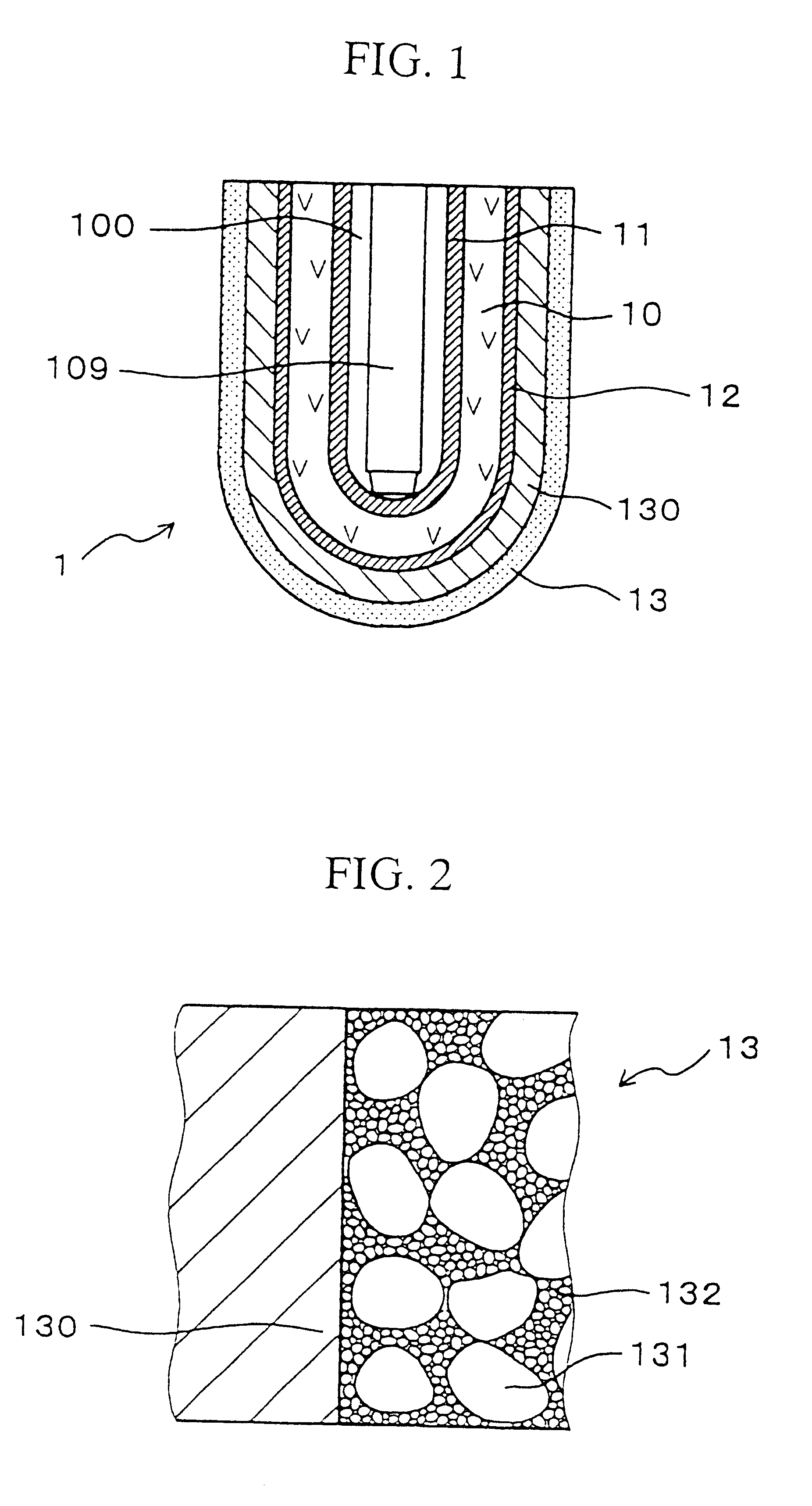
A first protective layer 130, coated by plasma spray, is provided on the surface of the measured gas sensing electrode 12. A second protective layer 13, made of a ceramic porous member, is provided on the surface of the first protective layer 130. The second protective layer 13 comprises coarse particles 131 and fine particles 132 structurally arranged in such a manner that interparticle cavities formed bet...

second embodiment

A second embodiment of the present invention is a gas sensing element whose protective layer contains a noble metallic catalyst as shown in FIG. 5.

The gas sensing element of the second embodiment is structurally similar to the gas sensing element of the first embodiment.

More specifically, the gas sensing element 1 of this embodiment comprises the solid electrolytic body 10 having an oxygen ionic conductance, the reference gas sensing electrode 11, and the measured gas sensing electrode 12 which cooperatively constitute an electrochemical cell. Air, serving as the reference gas, is introduced in the cup-shaped solid electrolytic body 10. An electric potential difference, representing an oxygen concentration difference between the reference gas and the measured gas, is produced between the gas sensing electrode 11 and the measured gas sensing electrode 12. In this respect, the gas sensing element 1 is a cell producing an electromotive force representing an air-fuel ratio of the measur...


PUM

PropertyMeasurementUnit
particle diameteraaaaaaaaaa
weight ratio WAaaaaaaaaaa

Abstract

A second protective layer is a ceramic porous protective layer comprising coarse particles and fine particles structurally arranged in such a manner that interparticle cavities formed between the coarse particles are filled with the fine particles. At least either of the coarse particles and the fine particles contain at least one selected from the group consisting of .gamma.-Al2O3, .theta.-Al2O3, .delta.-Al2O3 and solid solution having the same crystal structure as those of .gamma.-Al2O3, .theta.-Al2O3, .delta.-Al2O3.

Description

BACKGROUND OF THE INVENTIONThe present invention relates to a gas sensing element incorporated in a gas sensor used for controlling an air-fuel ratio of the gas mixture introduced into a combustion chamber of an internal combustion engine.In an automotive vehicle, a gas sensor is provided in an exhaust pipe of an internal combustion engine to control the air-fuel ratio of the gas mixture introduced into a combustion chamber of the engine.For example, a practical gas sensing element incorporated in the gas sensor is required to detect a concentration of oxygen gas contained in the exhaust gas. The gas sensing element may be formed by a ZrO2 solid electrolytic body which is capable of generating an electromotive force in accordance with the oxygen concentration.Japanese Patent No. HEI 2-15017 discloses a conventional gas sensing element whose output is responsive to an electromotive force.According to this type of conventional oxygen concentration detector, a gas sensing element is pr...

Claims


Application Information

Patent Timeline
Patent Type & Authority Patents(United States)
IPC IPC(8): G01N27/407G01N27/409G01N27/416
CPCG01N27/4077
Inventor FUJII, NAMITSUGUSATOU, MOTOAKIKOBAYASHI, KIYOMIHOTTA, YASUMICHI
Owner DENSO CORP
Why Eureka
Try Eureka