Axial gap motor-generator for high speed operation

a technology of axial gap and motor generator, which is applied in the direction of dynamo-electric machines, magnetic circuit rotating parts, magnetic circuit shape/form/construction, etc., can solve the problems of reducing system performance and lifetime, unwanted thermal signatures that can be utilized by hostile parties, and thermal generation also can be problematic, so as to achieve effective operation at high angular velocity

Inactive Publication Date: 2003-10-14
OPTIMAL ENERGY SYST
View PDF28 Cites 49 Cited by
  • Summary
  • Abstract
  • Description
  • Claims
  • Application Information

AI Technical Summary

Benefits of technology

Accordingly, an object of the present invention according to one aspect is to provide an axial gap motor-generator that is capable of operating effectively at high angular velocities, e.g., in excess of 10,000 RPM.

Problems solved by technology

This feature can be important in applications such as space-based power systems, wherein heat dissipation can be quite limiting and thermal accumulation can degrade system performance and lifetime.
Thermal generation also can be problematic with such applications as military weapon system power conversion subsystems.
Excess thermal energy generated during power conversion, aside from constituting an unwanted loss of precious energy, can result in unwanted thermal signatures that can be utilized by hostile parties to identify and possibly target the platform.
The generation of unwanted thermal energy also may be disadvantageous in that removal of such energy may require active cooling.
This requirement can place unwanted demands on space, weight, power and energy resources.
Axial gap motor-generators, however, have not been without limitations.
One such limitation is that, at the high rotational speeds often needed for sufficiently high power output levels, low heat loss levels, and low cooling requirements, for example, 10,000, and as high as 40,000 to 50,000 revolutions per minute (RPM), mechanical stresses are so substantial that failures are common.
One of the undesirable stresses placed on the system at high rotational speeds involves the substantial mechanical stress placed on the magnets used in the rotor.
High efficiency magnets capable of generating the large magnetic field strengths required for high performance applications, such as neodymium-iron-boron magnets, are relatively brittle.
Impact loading can cause them to crack and disintegrate at high rotational speeds.
Their ability to accommodate tension forces is particularly limited.
Another limitation of axial gap motor-generators has been that, at the relatively high rotational speeds required for advanced power conversion systems, they have a limited ability to accommodate the structural deformations that occur as the device reaches its intended operational speed or speed range.
Substantial flexure between the rotor and related components, for example, can change the geometry of the components responsible for converting power and the resultant magnetic field strength, thus causing inefficiencies and energy losses.
Excessive flexure in some instances can result in unwanted contacting of moving components, which can result in destruction of the motor-generator.
Axial gap motor-generators also have been limited in that the performance of the magnets typically used in such machines is degraded substantially by elevated temperatures.
Beyond that temperature range, their performance begins to degrade substantially and permanently.
A further limitation in many known axial gap motor-generators involves the presence of undesirable and problematic vibrations that arise in the device.

Method used


Image

  • Axial gap motor-generator for high speed operation
  • Axial gap motor-generator for high speed operation
  • Axial gap motor-generator for high speed operation

Examples


Embodiment Construction

Reference will now be made in detail to the presently preferred embodiments and methods of the invention as illustrated in the accompanying drawings, in which like reference characters designate like or corresponding parts throughout the drawings. It should be noted, however, that the invention in its broader aspects is not limited to the specific details, representative devices and methods, and illustrative examples shown and described in this section in connection with the preferred embodiments and methods. The invention according to its various aspects is particularly pointed out and distinctly claimed in the attached claims read in view of this specification, and appropriate equivalents.

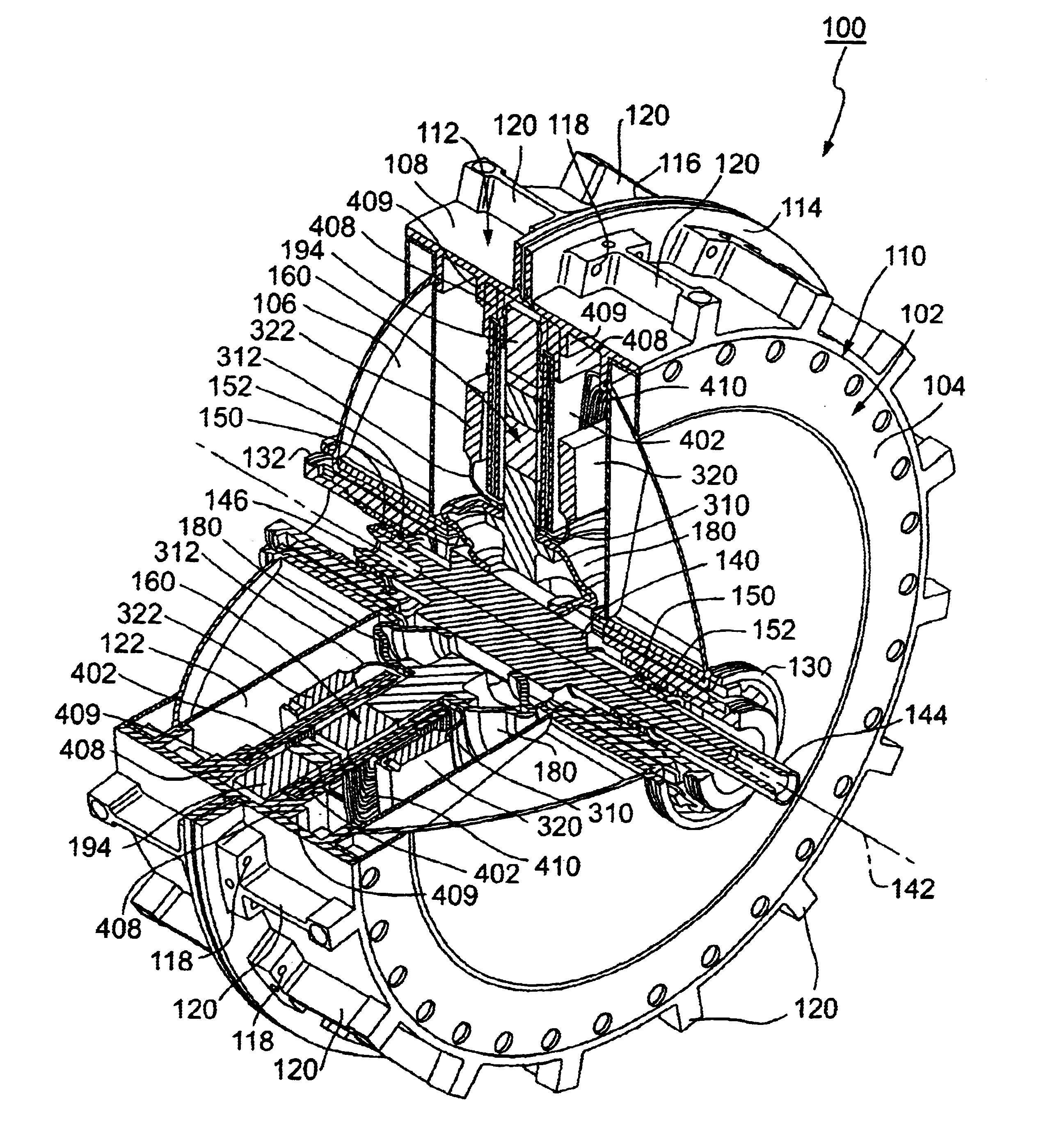
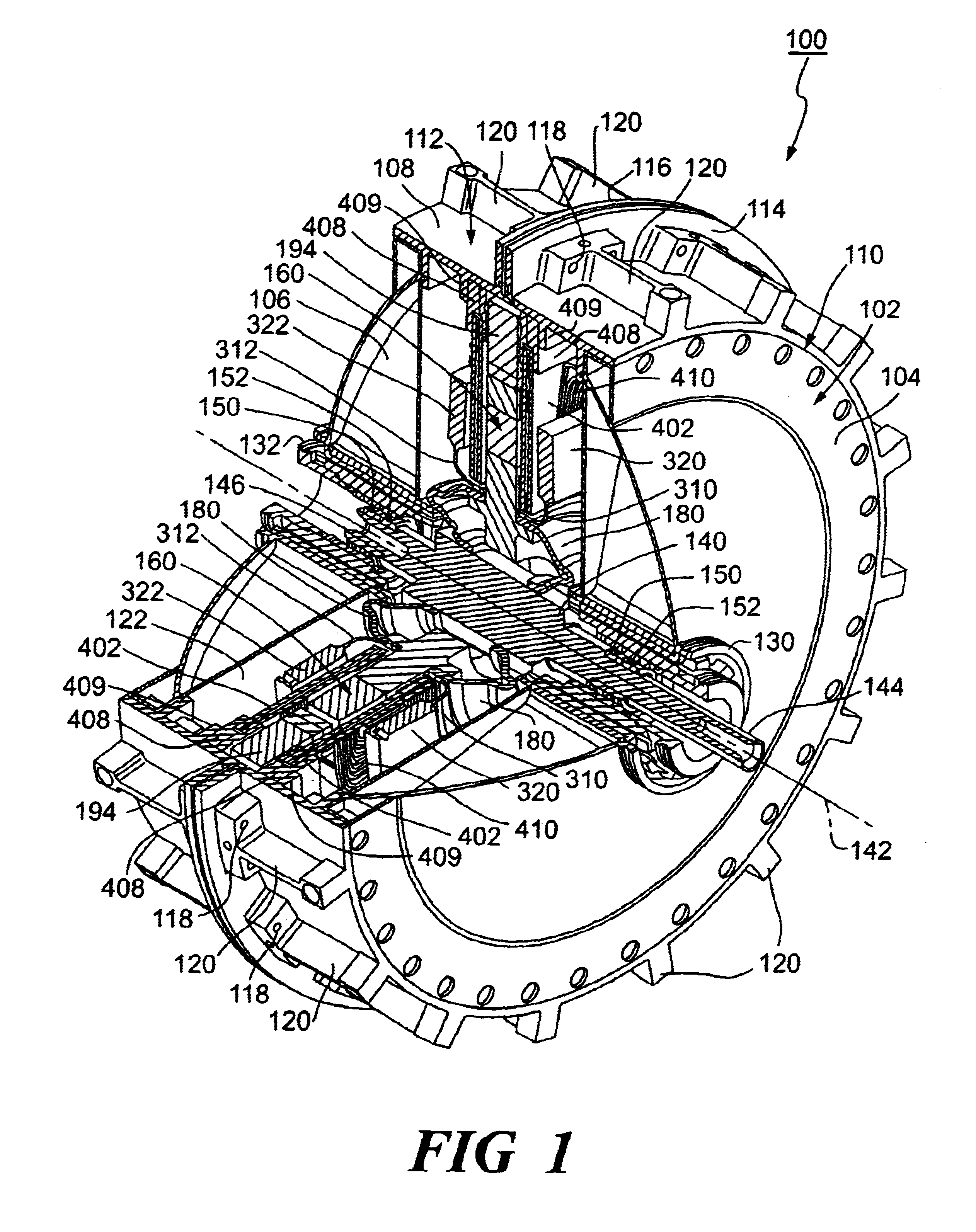
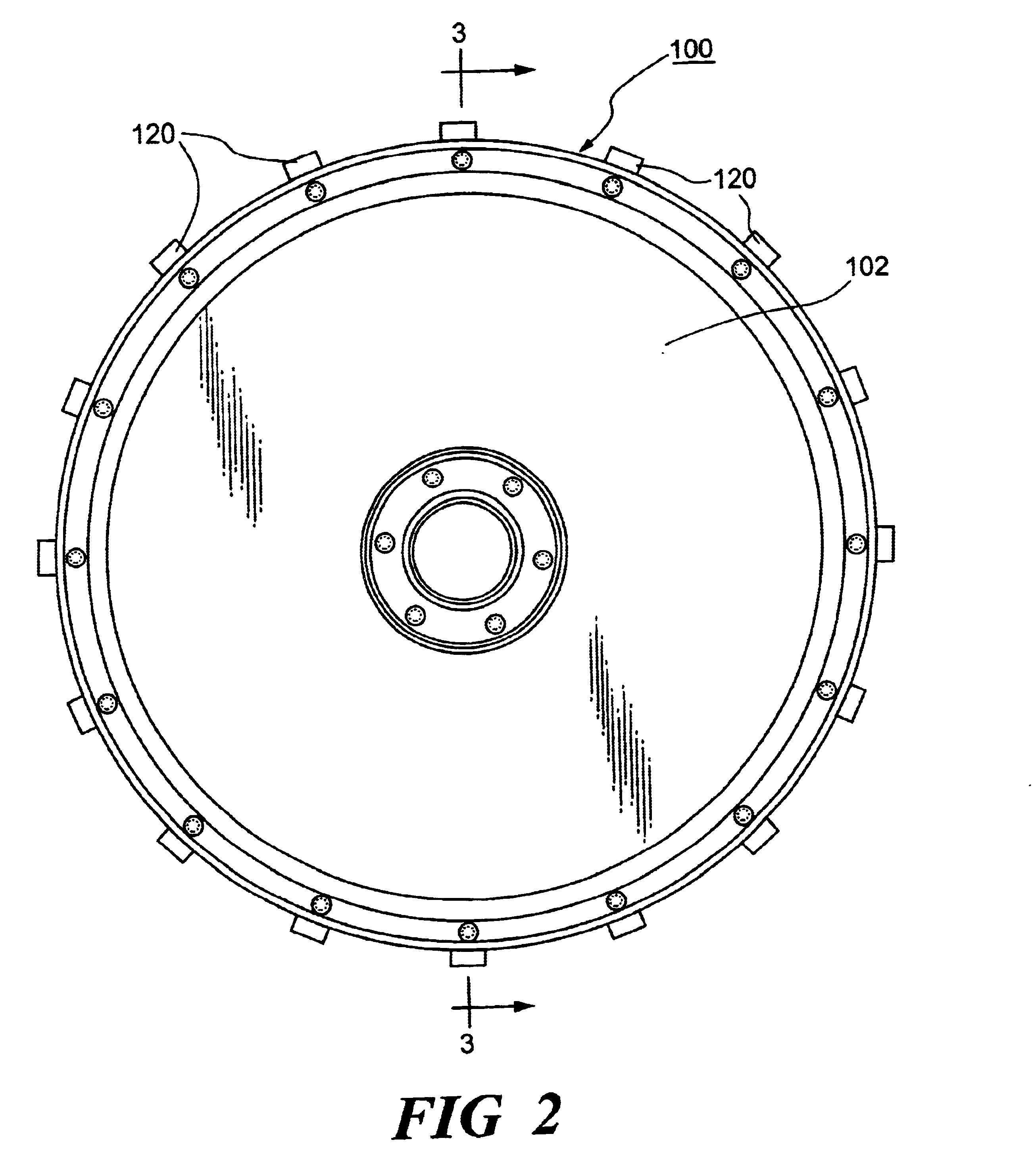
In accordance with one aspect of the invention, an axial gap motor-generator is provided. The axial gap motor-generator is of the type coupled to a shaft having an axis of rotation. The motor-generator may be used, for example, as a component in such applications as aerospace main power and auxil...


PUM


Abstract

An axial gap motor-generator of the type coupled to a shaft having an axis of rotation. The motor-generator comprises a rotor having a rotor body rotatably disposed about the shaft and having an outer region. The rotor includes a plurality of openings disposed in the outer region and spaced from one another. Each of the openings includes an outer edge. The motor-generator also includes a plurality of magnets equal in number to the openings. Each of the magnets includes an outer edge corresponding to the outer edge of a corresponding one of the openings. The outer edge of the magnets generally is non-conformal to and is slightly smaller than the outer edge of the openings, and each of the magnets is shaped to be inserted into the corresponding one of the openings. The motor-generator further includes a stator assembly positioned adjacent to the rotor. The stator assembly includes windings positioned to be adjacent to the magnets when the rotor is rotated. The outer edge of each of the magnets is dimensioned to substantially conform to the outer edge of the corresponding one of the openings when the axial gap motor-generator is operated at the operational speed and the outer edge of the corresponding one of the openings is thereby deformed. The motor-generator further includes a backiron assembly that is adapted to conform to the rotor when the rotor is operated at its operational state. A vibration isolator also is provided for isolating vibrations of the motor-generator from the shaft. Related methods also are provided.</PTEXT>

Description

1. Field of the InventionThe present invention relates to electrical generators and motors, and more specifically, to axial gap motor-generators and related components, systems and methods.2. Description of the Related ArtA need has existed for some time for small, light weight and efficient electrical machines that are capable of handing substantial power outputs without the need for elaborate external cooling systems. Applications for such devices include power conversion systems or subsystems for satellites, military vehicles and weapon systems, and the like.There has been a need for power conversion systems that can operate at high rotational speeds. There also has been a need for power conversion systems that generate relatively little heat. This feature can be important in applications such as space-based power systems, wherein heat dissipation can be quite limiting and thermal accumulation can degrade system performance and lifetime. Thermal generation also can be problematic...

Claims


Application Information

Patent Timeline
Patent Type & Authority Patents(United States)
IPC IPC(8): H02K5/173H02K1/27H02K21/12H02K1/28H02K21/24H02K1/30H02K5/24H02K7/02H02K16/00
CPCH02K1/2793H02K1/30H02K21/24H02K5/1732H02K5/24H02K1/2796
Inventor SWETT, DWIGHT W.
Owner OPTIMAL ENERGY SYST
Why Eureka
Try Eureka