High-frequency switch

a high-frequency switch and switch technology, applied in automatic frequency control, resonance circuit tuning, electrical equipment, etc., can solve the problem of increasing the loss of insertion between the transmission terminal tx and the antenna terminal an

Inactive Publication Date: 2003-10-14
MURATA MFG CO LTD
View PDF12 Cites 58 Cited by
  • Summary
  • Abstract
  • Description
  • Claims
  • Application Information

AI Technical Summary

Problems solved by technology

When this isolation is poor, insertion loss between the tran

Method used


Image

  • High-frequency switch
  • High-frequency switch
  • High-frequency switch

Examples


embodiment 1

, FIG. 1 to FIG. 3

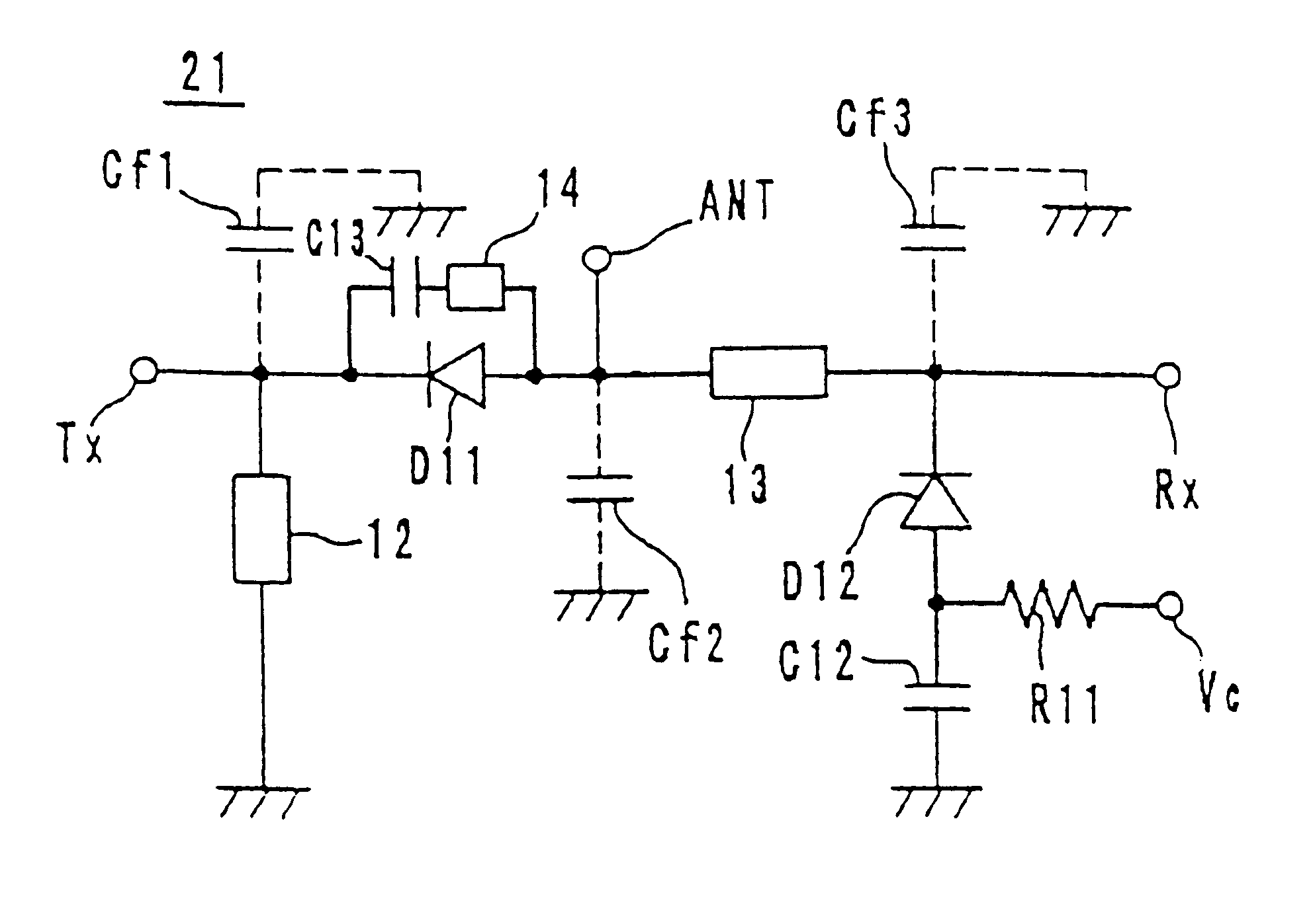
FIG. 1 is an electrical circuit diagram showing an example of a high-frequency switch 21 according to the present invention. The cathode of a diode D11, forming a switching element, is connected to a transmission terminal Tx. The cathode of the diode D11 is grounded via a transmission line 12. The transmission line 12 functions as a choke element. In addition, the anode of the diode D11 connects to an antenna terminal ANT.

A reception terminal Rx is connected via a transmission line 13 to the antenna terminal ANT. Moreover, the cathode of a diode D12 connects to the reception terminal Rx. The anode of the diode D12 connects to the ground via a DC-blocking capacitor C12. A voltage-control terminal Vc connects via a resistor R11 to an intermediate connection point between the diode D12 and the capacitor C12. A control circuit (not shown) is connected to this voltage-control terminal Vc, and switches the transmission lines of the high-frequency switch 21.

A series circu...

embodiment 2

, FIG. 4 and FIG. 5

Another example of a multilayered high-frequency switch having the electrical circuit shown in FIG. 1 will be explained referring to FIG. 4 and FIG. 5. The high-frequency switch 61 of this second embodiment contains a DC-blocking capacitor C12 within its multilayered body. In FIGS. 4 and 5, the same parts as those in FIGS. 2 and 3 are represented by the same reference numerals, and explanation thereof is omitted.

As shown in FIG. 4, the high-frequency switch 61 comprises a dielectric sheet 45j; comprising a distributed constant line 62 and a capacitor electrode 70, dielectric sheets 45d and 45g comprising wide-area ground electrodes 35 and 36, a dielectric sheet 45k comprising distributed constant lines 63 and 64, a dielectric sheet 45i; comprising extracted electrodes 37 and 38 and the like, a dielectric sheet 45h comprising peer-hole pads 50a and 50b and the like, etc.

The distributed constant line 62 is for instance meander-shaped, and forms a transmission line 1...


PUM


Abstract

A high-frequency switch includes a transmission terminal, an antenna terminal, a reception terminal, and a voltage-control terminal; a first diode, the cathode thereof being electrically connected to the transmission terminal, and the anode being electrically connected to the antenna terminal; a first transmission line, electrically connected between the antenna terminal and the reception terminal; a second diode, the cathode thereof being electrically connected to the reception terminal, and the anode being electrically connected to the voltage-control terminal; a second transmission line, one end thereof being electrically connected to the transmission terminal, and the other end being connected to ground; and a capacitor, electrically connected between the voltage-control terminal and ground. The above high-frequency switch can be miniaturized and has superior performance.</PTEXT>

Description

1. Field of the InventionThe present invention relates to a high-frequency switch, and more particularly to a high-frequency switch for being incorporated in a mobile communications device and the like.2. Description of the Related ArtA high-frequency switch is generally used for switching between a transmission circuit and a reception circuit in a digital mobile telephone and the like. FIG. 6 is an electrical circuit diagram showing a prior art high-frequency switch 1. The anode of a diode D1 is connected to a transmission terminal Tx. The anode of the diode D1 is grounded via a series circuit comprising a transmission line 2 and a DC-blocking capacitor C1. A voltage-control terminal Vc1 is connected via a resistor Ra at an intermediate connection point between the transmission line 2 and the capacitor C1. The cathode of the diode D1 connects to an antenna terminal ANT.A reception terminal Rx is connected to the antenna terminal ANT via a transmission line 3. Moreover, the anode of...

Claims


Application Information

Patent Timeline
IPC IPC(8): H03J7/00H04B1/44H01P1/10H04B1/48H01P1/15
CPCH04B1/48H03J7/00
Inventor KATO, MITSUHIDE
Owner MURATA MFG CO LTD
Why Eureka
Try Eureka