Fuze explosive train device and method

a technology of explosive train and firing mechanism, which is applied in the direction of ammunition fuzes, hand grenades, weapons, etc., can solve the problems of reducing the efficiency of the warhead, pyrotechnic delays, and timing accuracy and reliability may not be as high as other methods, so as to achieve precise control of mechanical delays and accurate control of delay mechanisms

Inactive Publication Date: 2003-11-04
UNITED STATES OF AMERICA THE AS REPRESENTED BY THE SEC OF THE ARMY
View PDF9 Cites 27 Cited by
  • Summary
  • Abstract
  • Description
  • Claims
  • Application Information

AI Technical Summary

Benefits of technology

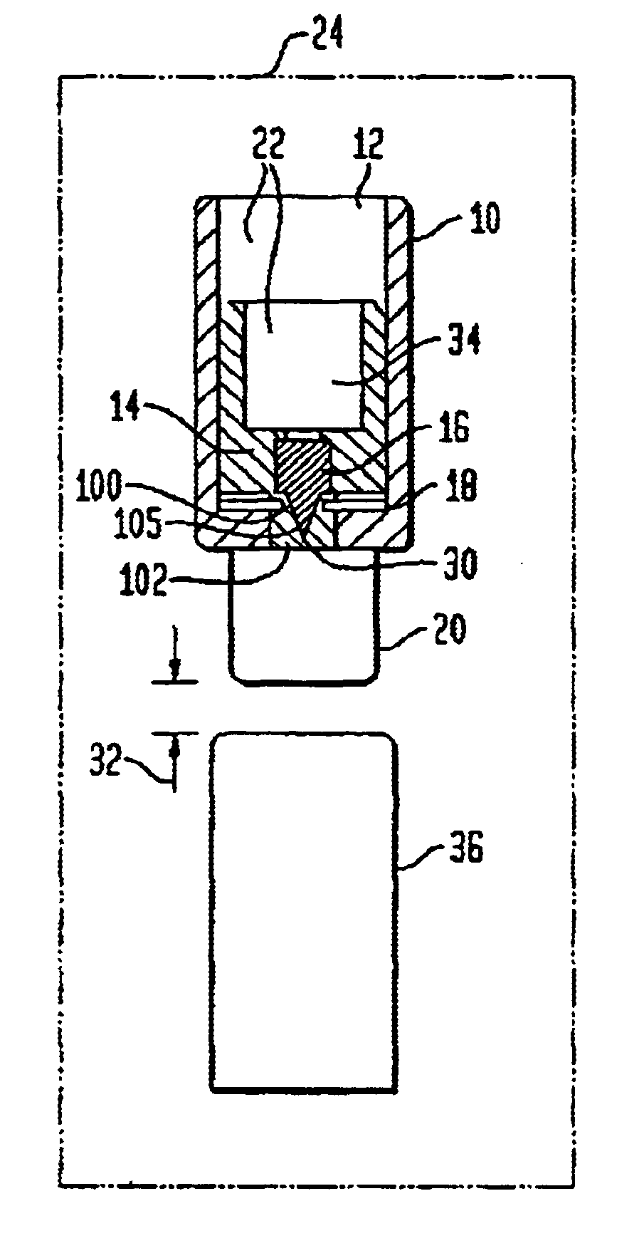
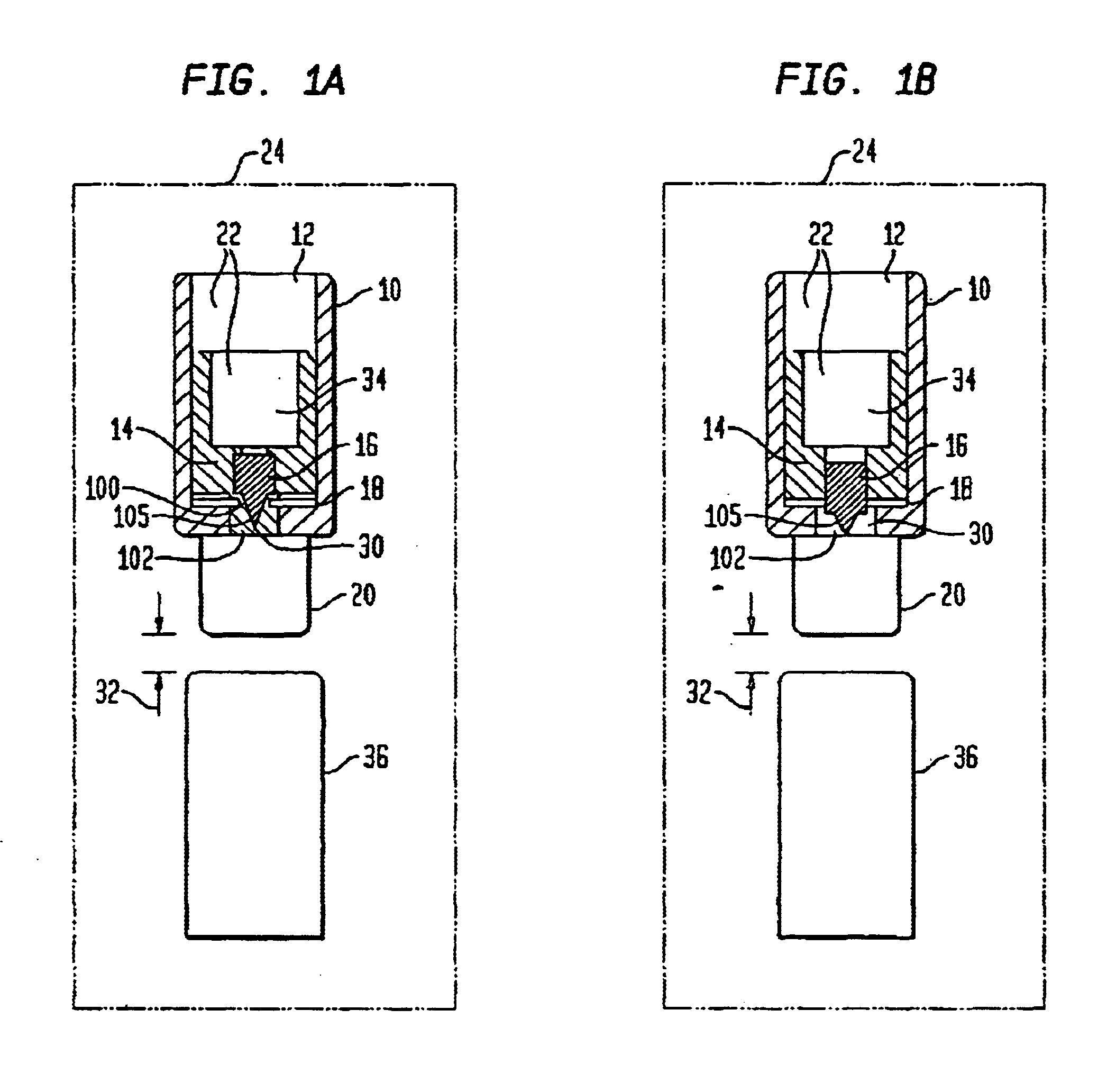
The supporting disk is an important part of the fuze explosive train device in that it seats and supports the stab firing pin, and further allows for a controlled mechanical delay upon rupture, which feature is lacking in conventional fuze explosive train devices. The disk is generally flat and circular in shape.
The rupturing of the supporting disk is also an important aspect of the fuze explosive train device as it allows for a very precise control of the mechanical delay, by controlling the m...

Problems solved by technology

However, a time delay that is either too rapid or too slow drastically reduces the efficiency of the warhead.
Pyrotechnic delays are inexpensive although timing accuracy and reliability may not be as high as other methods.
Problems arise in trying to make pyrotechnic delays short, such as delays of less than about 1 millisecond.
Such a delay, while theoretically possible, would be near impossible to manufacture.
A 2 millisecond delay using a high explosive, such as HNS as a delay medium which has reaction rates much faster than a pyrotechnic delay blend...

Method used


Image

  • Fuze explosive train device and method
  • Fuze explosive train device and method
  • Fuze explosive train device and method

Examples


example 1

In a laboratory, 234 fuzes were tested that contained the stab firing pin incorporated into the pressure cartridge. The gap between the detonator and the lead was held at a range of from about 0.030 inches to about 0.060 inches, and the gap between the stab firing pin and stab detonator was held at a range of from about 0.005 inches to about 0.030 inches. The stab firing pins were held in place by a single supporting disk, with the disk rupturing 100 percent of the time. There were no low order functions observed in the test. The fuzes demonstrated a 99.1 percent reliability, with a 90 percent confidence.

example 2

Example 1 was conducted using two disks within each fuze to hold the stab firing pins. Several of the fuzes worked, however, at least one failure was noted indicating the need to ensure single disk installation to secure the stab firing pin.


PUM


Abstract

A fuze explosive train device for detonating a munition that uses a stab firing pin within a pressure cartridge, with the stab firing pin located between a gas generator and a stab detonator. The firing pin is capable of transferring an energy from the gas generator into the stab detonator in a manner that initiates the stab detonator to a high order explosive reaction. A method of initiating a stab detonator using a stab firing pin also is disclosed.

Description

1. Field of the InventionThe present invention relates to a firing mechanism for munition rounds. More particularly, the firing mechanism uses an assembly with a stab firing pin to delay detonation of a munition round after initial contact with a target. The stab firing pin is seated within a supporting disk in a pressure cartridge for proper and reliable firing of the munition warhead.2. Background ArtThe survival of a military unit depends to a great extent on its ability to defeat enemy armor and field fortifications. Substantial improvements in the effectiveness of armor and fortifications to withstand exploding munitions has occurred. Layered defenses and reinforced structures are generally designed to deflect the explosive force of a munition away from a target, or to absorb part of the destructive force as a way to dissipate the damaging effects of the munition. Munitions with a delayed warhead detonation, after target impact, have increased effectiveness in damaging or destr...

Claims


Application Information

Patent Timeline
IPC IPC(8): F42C15/00F42C15/31
CPCF42C15/31
Inventor PACELLA, GARY A.SCHWARTZ, BARRY D.
Owner UNITED STATES OF AMERICA THE AS REPRESENTED BY THE SEC OF THE ARMY
Why Eureka
Try Eureka