Storage apparatus, card type storage apparatus, and electronic apparatus

a technology of electronic equipment and storage equipment, applied in the field of storage equipment, can solve the problems of not being suitable for portable equipment, wireless terminals without detachable storage equipment, and floppy disks not being suitable for electronic equipmen

Inactive Publication Date: 2003-11-04
KK TOSHIBA
View PDF44 Cites 31 Cited by
  • Summary
  • Abstract
  • Description
  • Claims
  • Application Information

AI Technical Summary

Benefits of technology

Another object of the present invention is to provide a storage apparatus that has compatibility with other electronic apparatuses of prior generations and that has small, thin, and light structure.
In the electronic apparatus according to the present invention, the storage apparatus can be properly attached to the electronic apparatus. Thus, when the storage apparatus is connected to a host side electronic apparatus such as a portable telephone unit, a PHS unit, a pocket bell, a PDA, a PC, or a digital camera, the electronic apparatus can be prevented from malfunctioning or being damaged. In addition, the user-friendliness remarkably improves. So far, it was difficult to accomplish an external connecting unit that can be used in common with a portable telephone unit, a PHS unit, a pocket bell, a PDA unit, a digital camera, a note type PC, a PC, and so forth. However, with the storage apparatus and the electronic apparatus according to the present invention, data such as telephone numbers registered to a portable telephone unit, text data, picture data, and so forth received through Internet can be transferred to and shared with other information processing units.

Problems solved by technology

Thus, the floppy disk could not be a medium suitable for an electronic apparatus that is small and light.
However, such wireless terminals do not have detachable storage apparatuses.
Thus, when a wireless terminal such as a portable telephone unit or a PHS unit is replaced with a new model, the directory and various settings of the old unit may not be used for the new unit.
However, the size and weight of the digital camera depend on those of the floppy disk.
Thus, since the digital camera becomes large and heavy, it is not suitable as a portable apparatus.
The storage apparatuses that such portable electronic apparatuses have do not satisfy both requirements of compatibility with other electronic apparatuses of prior generations and small / light structure necessary for portable apparatuses.
Thus, the strength of the storage apparatus deteriorates.
On the other hand, when a convex pattern is formed, since the thickness of the storage apparatus becomes large, the requirement for small and thin structure cannot be satisfied.
In addition, with the molding resin having one or plural notches the storage apparatus is unsymmetrically shaped and voltage display function or discrimination function and the like is provided.
So far, it was difficult to accomplish an external connecting unit that can be used in common with a portable telephone unit, a PHS unit, a pocket bell, a PDA unit, a digital camera, a note type PC, a PC, and so forth.

Method used


Image

  • Storage apparatus, card type storage apparatus, and electronic apparatus
  • Storage apparatus, card type storage apparatus, and electronic apparatus
  • Storage apparatus, card type storage apparatus, and electronic apparatus

Examples


first embodiment

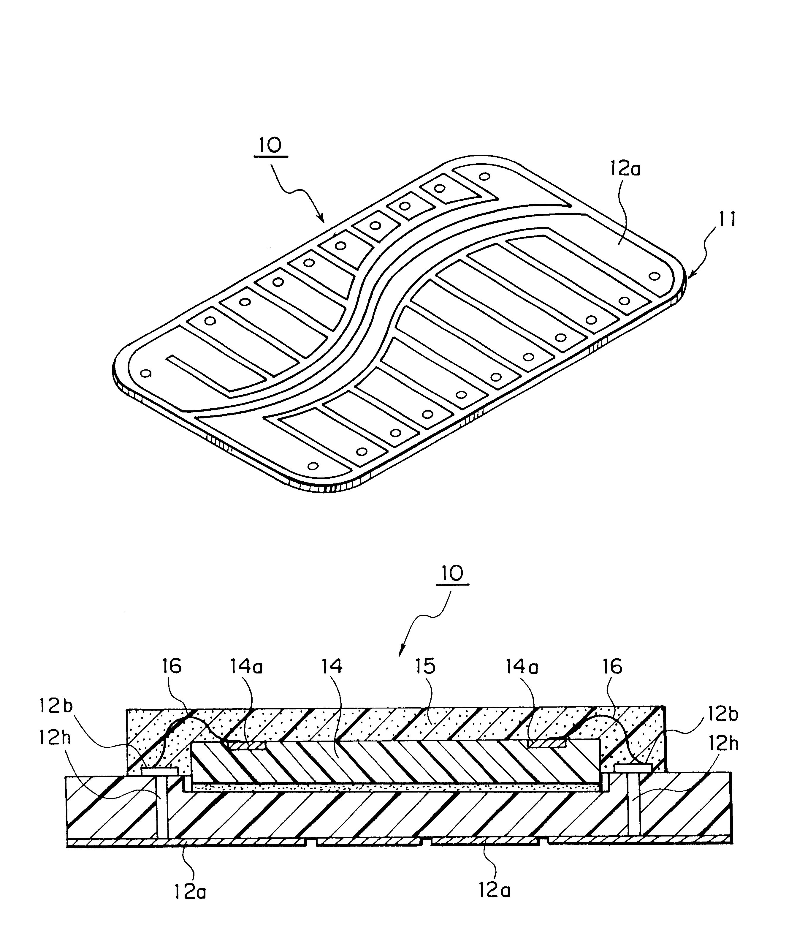
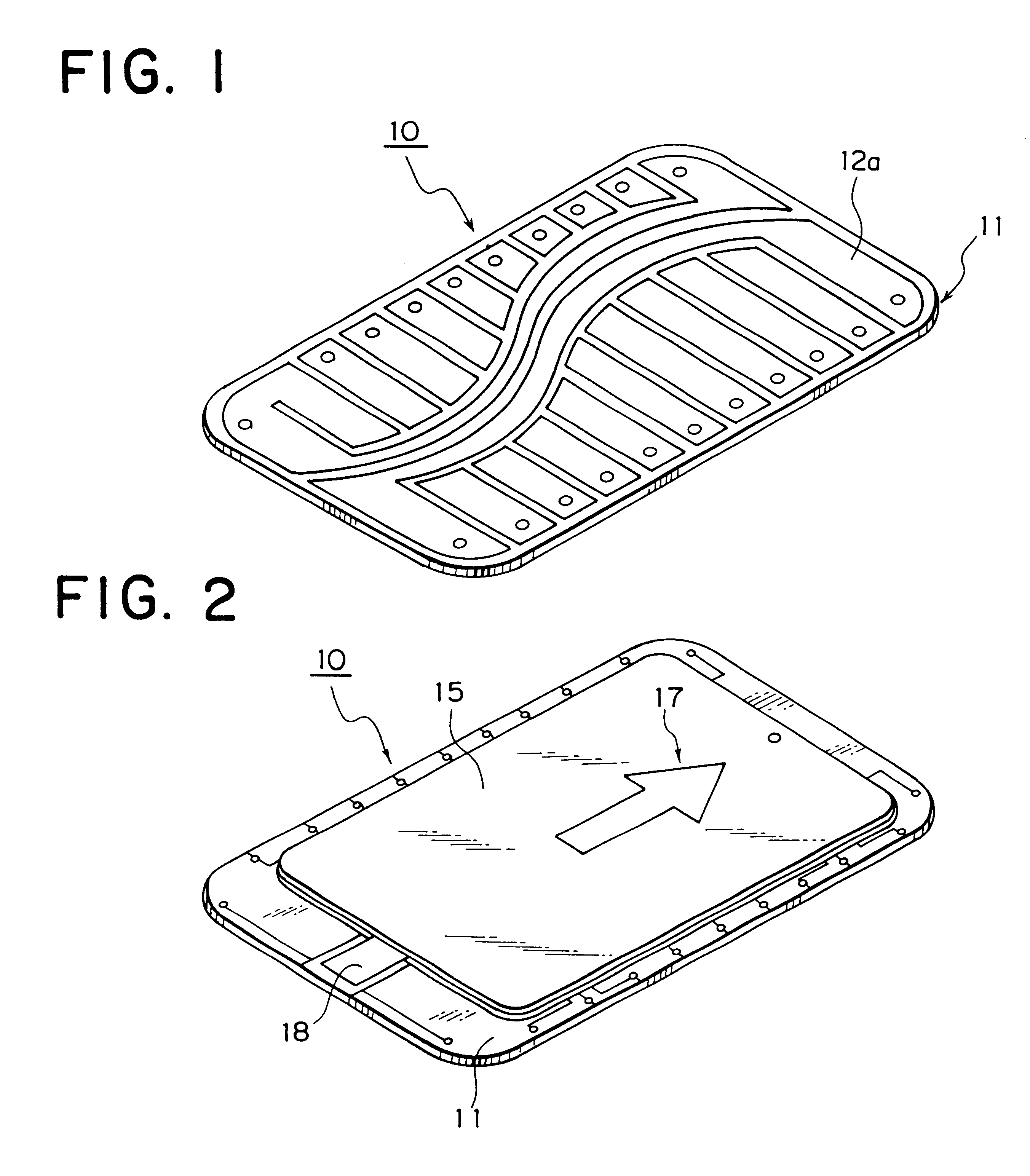
FIGS. 1 and 2 are a perspective front view and a perspective rear view showing an example of the structure of a storage apparatus according to a first embodiment of the present invention, respectively.

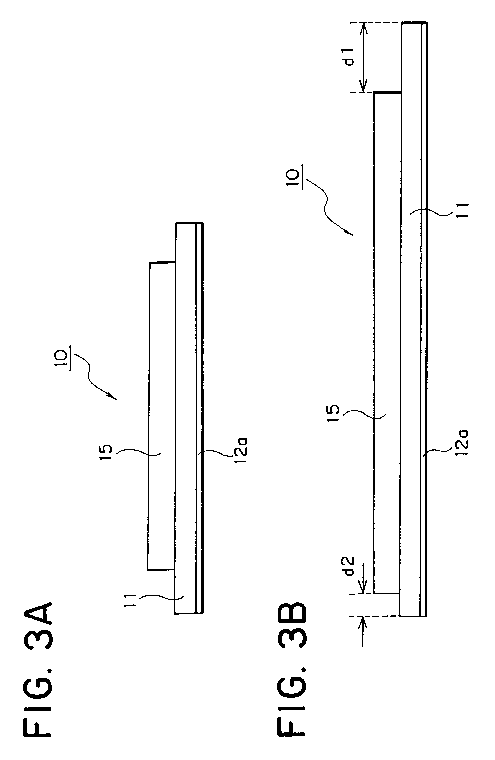
FIG. 3A is a sectional view on a shorter side of the storage apparatus shown in FIGS. 1 and 2. FIG. 3B is a sectional view on a longer side of the storage apparatus shown in FIGS. 1 and 2.

FIG. 4 is a detailed sectional view showing an example of the structure of the storage apparatus parallel to the first embodiment of the present invention on a shorter side.

In FIG. 4, reference numeral 10 is a storage apparatus. The storage apparatus 10 comprises a wiring substrate 11, a flat type external connection terminal 12a, a semiconductor device 14, and molding resin 15. The wiring substrate 11 has a first surface and a second surface. The flat type external connection terminal 12a is disposed on the first surface of the wiring substrate 11. The semiconductor device 14 is disposed on the secon...

second embodiment

FIG. 5A is a perspective view showing an example of the structure of a card type storage apparatus according to a second embodiment of the present invention, and FIG. 5B is a perspective view showing a support card of the card type storage apparatus.

In the card type storage apparatus, the storage apparatus according to the first embodiment of the present invention is held by a support card.

In FIGS. 5A and 5B, reference numeral 20 is a card type storage apparatus 20 according to the second embodiment of the present invention. The card type storage apparatus 20 comprises a storage apparatus 10 according to the first embodiment of the present invention and a support card 21. The support card 21 detachably supports the storage apparatus 10 in such a manner that the flat type external connection terminal 12a is exposed.

The support card 21 has a concave portion 22 that supports the storage apparatus 10. The concave portion 22 is formed so that it fits the shape of the molding resin 15 of ...

third embodiment

FIGS. 6 and 7 are sectional views showing an example of the structure of an electronic apparatus according to a third embodiment of the present invention.

FIG. 6 shows the state of which the storage apparatus 10 is detached from the electronic apparatus 30 according to the present invention. FIG. 7 shows the state of which the storage apparatus 10 according to the present invention is attached to the electronic apparatus 30 according to the present invention.

The electronic apparatus 30 comprises a concave portion 31, a connection electrode 32, and a driving circuit (not shown). The concave portion 31 supports the storage apparatus according to the present invention. When the storage apparatus 10 is supported with the concave portion 31, the connection electrode 32 is connected to the flat type connection terminal 12a of the storage apparatus 10. The driving circuit drives the semiconductor device 14 through the connection electrode 32 and the flat type external connection terminal 12...


PUM


Abstract

A storage apparatus 10 is disclosed, that comprises a wiring substrate 11 having a first surface and a second surface, a flat type external connection terminal 12a disposed on the first surface of the wiring substrate 11, a semiconductor device 14 disposed on the second surface of the wiring substrate 11 and having a connection terminal 14a connected to the flat type external connection terminal 12a, a molding resin 15 for coating the semiconductor device 14 on the second surface of the wiring substrate 11, a card type supporting frame 10a having a concave portion or a hole portion fitting the wiring substrate 11, the semiconductor device 14, and the molding resin 15 in such a manner that the flat type external connection terminal 12a is exposed to the first surface of the wiring substrate 11, and adhesive resin a adhering integrally the flat type external connection terminal 12a, the wiring substrate 11, the semiconductor device 14, the molding resin 15, and the card type supporting frame 10a. In addition, the storage apparatus 10 can be combined with a card type supporting means 21 that supports detachably with the flat type external connection terminal 12a exposed to one of the surfaces so as to be used as a card type storage apparatus 20 having bigger size.

Description

1. Field of the InventionThe present invention relates to a storage apparatus, in particular, to a backward compatible storage apparatus suitable for transferring and exchanging digital information between various portable electronic apparatuses. In addition, the present invention relates to a card type storage apparatus, in particular, to a card type storage apparatus suitable for transferring and exchanging digital information between various portable electronic apparatuses.Moreover, the present invention relates to various portable wireless terminals such as a personal computer, a portable information terminal, a portable telephone unit, and a PHS (Personal Handyphone System) unit and various electronic apparatuses such as a digital camera and a voice recorder.2. Description of the Related ArtIn recent years, various types of information such as characters, still pictures, moving pictures, music, and voice are handled as digital data. Various types of storage mediums such as a ma...

Claims


Application Information

Patent Timeline
Patent Type & Authority Patents(United States)
IPC IPC(8): H01L23/498H01L23/48H01L23/28H01L23/31
CPCG06K19/07739G06K19/07743H01L23/3121H01L23/49855H01L2224/73265H01L2224/48227H01L2224/48091H01L24/48H01L2924/15165H01L2924/15153H01L2924/01079H01L2224/4847H01L2224/48472H01L2924/00014H01L2924/00H01L2924/181H01L2224/05599H01L2224/85399H01L2924/00012H01L2224/45099H01L2224/45015H01L2924/207H01L23/28
Inventor IWASAKI, HIROSHI
Owner KK TOSHIBA
Why Eureka
Try Eureka