Method to affect spatial distribution of harmonic generation in a capacitive discharge reactor

a capacitive discharge and spatial distribution technology, applied in the field ofplasma processing, can solve the problems of poor yield, uniform etching of workpieces, and inability to uniformly process workpieces

Inactive Publication Date: 2003-11-04
TOKYO ELECTRON LTD
View PDF12 Cites 28 Cited by
  • Summary
  • Abstract
  • Description
  • Claims
  • Application Information

AI Technical Summary

Problems solved by technology

The use of such a nonuniform plasma can result in a workpiece that is not uniformly processed.
A nonuniformly etched workpiece is undesirable in most plasma processing, and in many cases can have poor yield, or must be discarded.

Method used


Image

  • Method to affect spatial distribution of harmonic generation in a capacitive discharge reactor
  • Method to affect spatial distribution of harmonic generation in a capacitive discharge reactor

Examples


Embodiment Construction

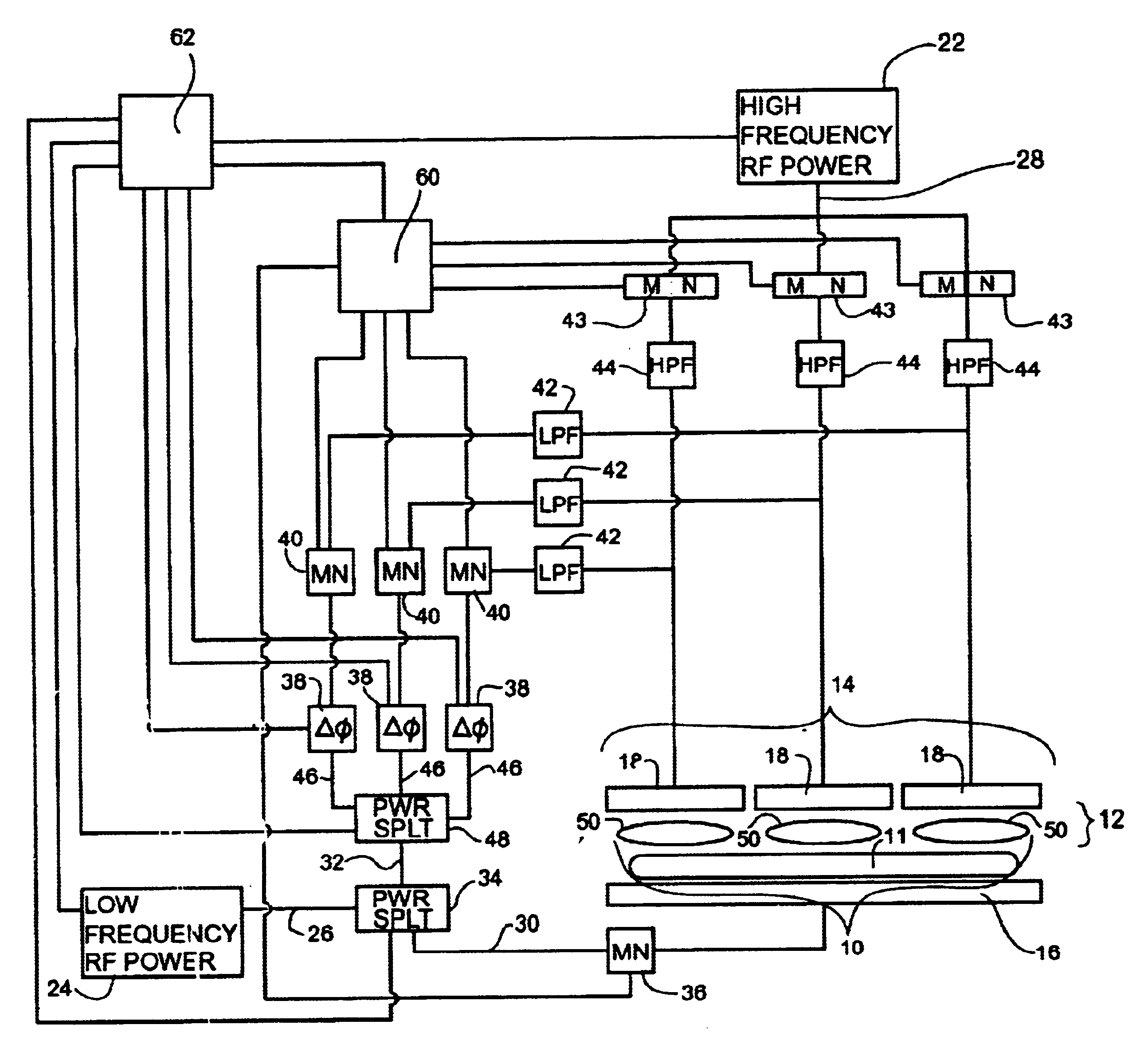
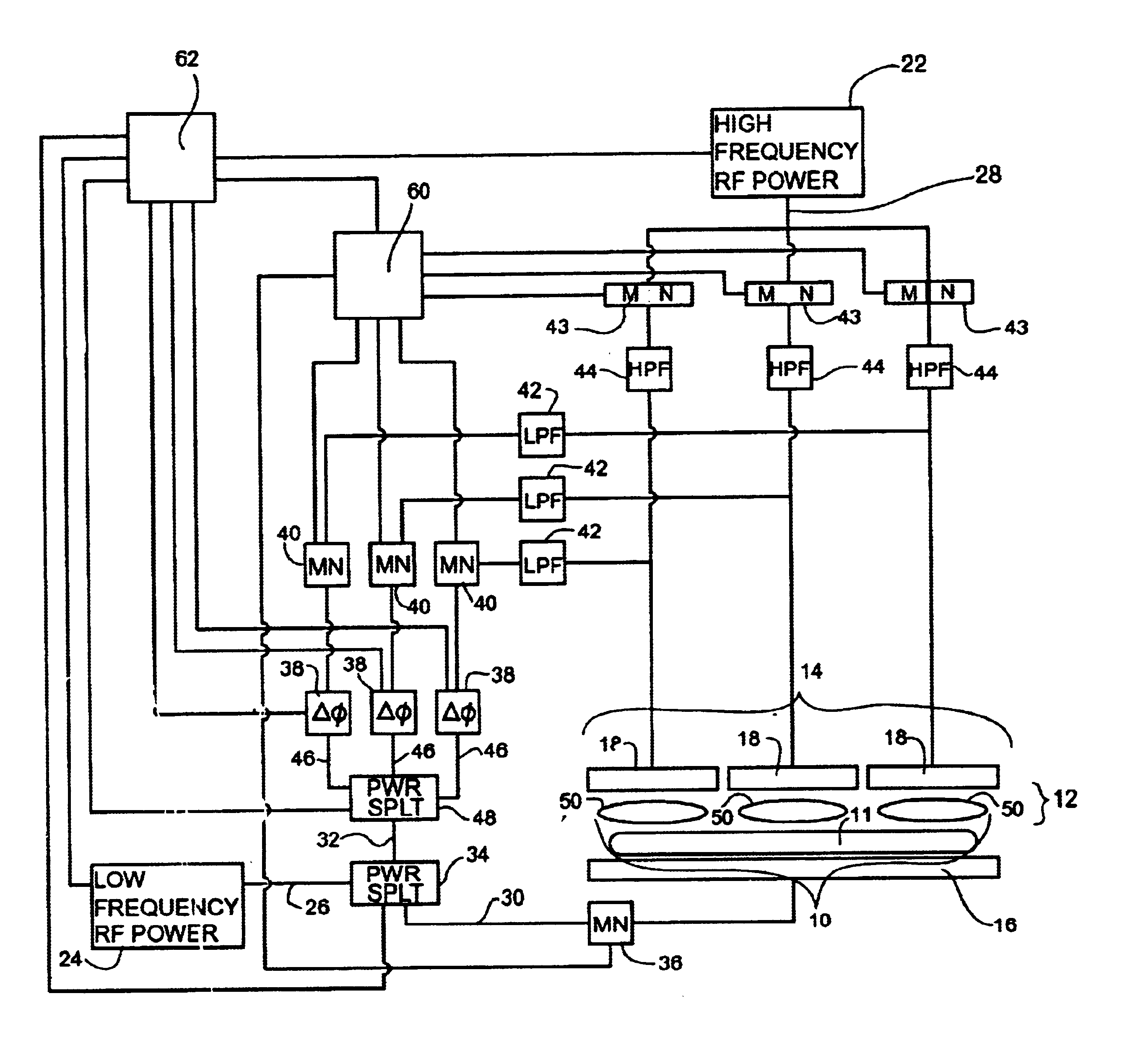
The figure shows the structure of a capacitively coupled plasma reactor according to the present invention. Two parallel electrodes 14, 16 forming capacitor plates are arranged opposed to one another. The electrode 14 is segmented and is supplied with a high-frequency signal. Electrode 16 is supplied with a low-frequency signal. The bias electrode 16 can act as a holder (i.e., a chuck) for the workpiece 11 that is to be etched. A gas source and exhaust, not shown, allow gas to enter the plasma generation region 12 between the plasma electrode 14 and the bias electrode 16. The plasma electrode 14 and the bias electrode 16 are excited by one or more radio frequency power supplies 22, 24 to generate plasma 10 in the plasma region 12 of the plasma reactor. Typically, the plasma electrode 14 can be excited at a primary frequency of 60 MHz, and the bias electrode 16 can be excited at a frequency of 2 MHz. One aspect of the present invention involves applying a portion of the lower frequen...


PUM

PropertyMeasurementUnit
frequencyaaaaaaaaaa
frequencyaaaaaaaaaa
electric poweraaaaaaaaaa

Abstract

The present invention provides an apparatus and a method of generating and controlling plasma formed in a capacitively coupled plasma region between a plasma electrode and a bias electrode. The plasma electrode includes a plurality of sub-electrodes that are electrically insulated from one another. Radio frequency plasma generating electric power is provided to the plasma electrode. Radio frequency bias electric power, at a lower frequency than the plasma generating radio frequency electric power, is also provided. A first portion of the bias electric power is provided to the bias electrode, and a second portion of the bias electric power is provided to the plasma electrode. At least one filter, impedance matching network, phase shifter, and power splitter are used to affect the electric power provided to the electrodes.

Description

1. Field of the InventionThis invention relates generally to the field of plasma processing, and more particularly to capacitively coupled discharge plasma reactors.2. Description of Related ArtCapacitive discharge plasma reactors are widely used to process semiconductor substrates, display substrates or the like. In these reactors, a plasma is formed when a gas (or gas mixture) is energized, leaving a mixture of charged and uncharged particles. The plasma can then be used to etch or form a deposit on a substrate.A typical capacitive discharge plasma reactor uses a high-frequency electrode and a low-frequency electrode to generate plasma. These two electrodes are placed opposed to one another, spaced a short distance apart within a sealable chamber. This placement of the two electrodes forms a classic parallel plate capacitor, in which the low-power electrode acts as a holder (i.e., a chuck) for the workpiece to be processed.During the operation of the plasma reactor, a gas or mixtu...

Claims


Application Information

Patent Timeline
Patent Type & Authority Patents(United States)
IPC IPC(8): H01J37/32
CPCH01J37/32091H01J37/32706H01J37/32174
Inventor STRANG, ERIC J.
Owner TOKYO ELECTRON LTD
Why Eureka
Try Eureka