
Engine braking system

a technology of engine braking and braking system, which is applied in the direction of machines/engines, output power, non-mechanical valves, etc., can solve the problems of increasing the size of the engine, the gross weight of the associated vehicle, and the cost of the manufacturer and the user

Inactive Publication Date: 2003-11-11
CATERPILLAR INC
View PDF16 Cites 11 Cited by
  • Summary
  • Abstract
  • Description
  • Claims
  • Application Information

AI Technical Summary

Benefits of technology

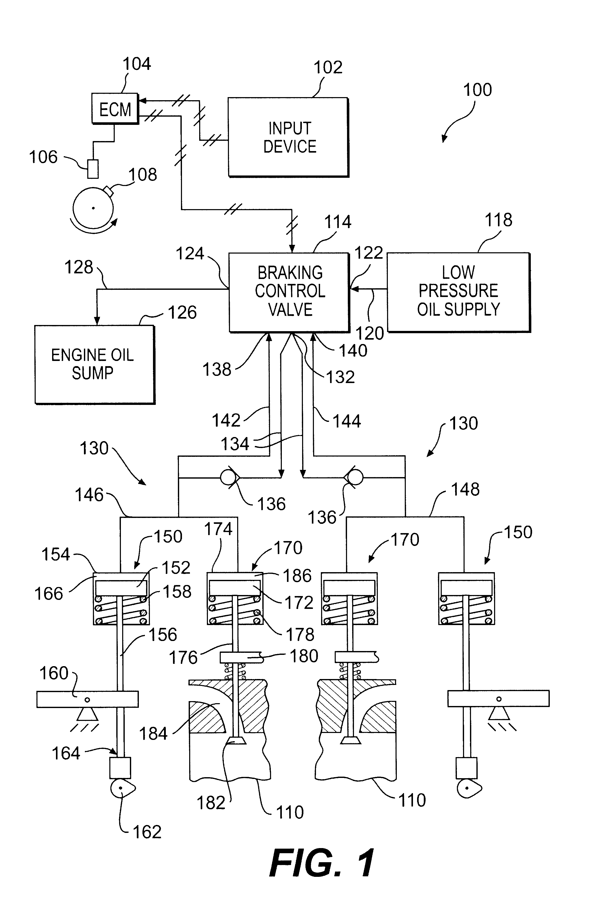
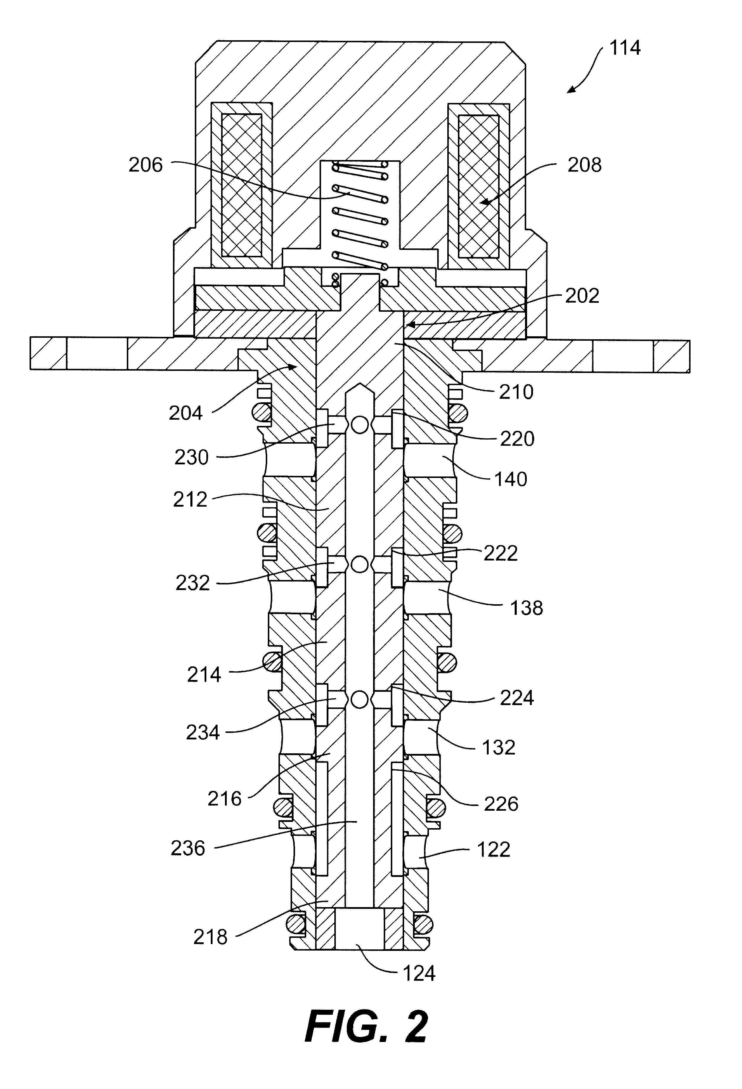
In accordance with one aspect of the invention, an engine braking system for a multi-cylinder engine includes a supply of low pressure fluid and an engine fluid sump. A plurality of valve actuators are each configured to be alternatively fluidly coupled to the supply of low pressure fluid and the engine fluid sump. Each valve actuator is operably coupled to at least one exhaust valve for a respective cylinder. The system also includes a braking control valve operably coupled to two of the valve actuators. The braking control valve is movable between a first position at which the two valve actuators are fluidly coupled to the engine fluid sump and blocked from the supply of low pressure fluid and a second position at which the two valve actuators are fluidly coupled to the supply of low pressure fluid and blocked from the engine fluid sump.
In accordance with another aspect of the invention, an engine braking method for a multi-cylinder engine is provided. Compressed air from the compression stroke of a cylinder is used for engine braking and the compressed air is released through a cylinder exhaust valve near a piston top-dead-center position. The method includes supplying fluid from a supply of low pressure fluid to a braking control valve and selectively controlling movement of the braking control valve between a first position at which two valve actuators are fluidly

Problems solved by technology

Thus, the Cummins device requires manufacture, assembly, warranty, and maintenance of these numerous valves.
Each of these concerns comes at an expense to the manufacturer and the user.
Furthermore, the numerous valves and associated plumbing occupy space in the engine compartment, thus increasing the size of the engine, the weight of the engine, and the gross weight of the associated vehicle.

Method used


Image

  • Engine braking system
  • Engine braking system
  • Engine braking system

Examples


Embodiment Construction

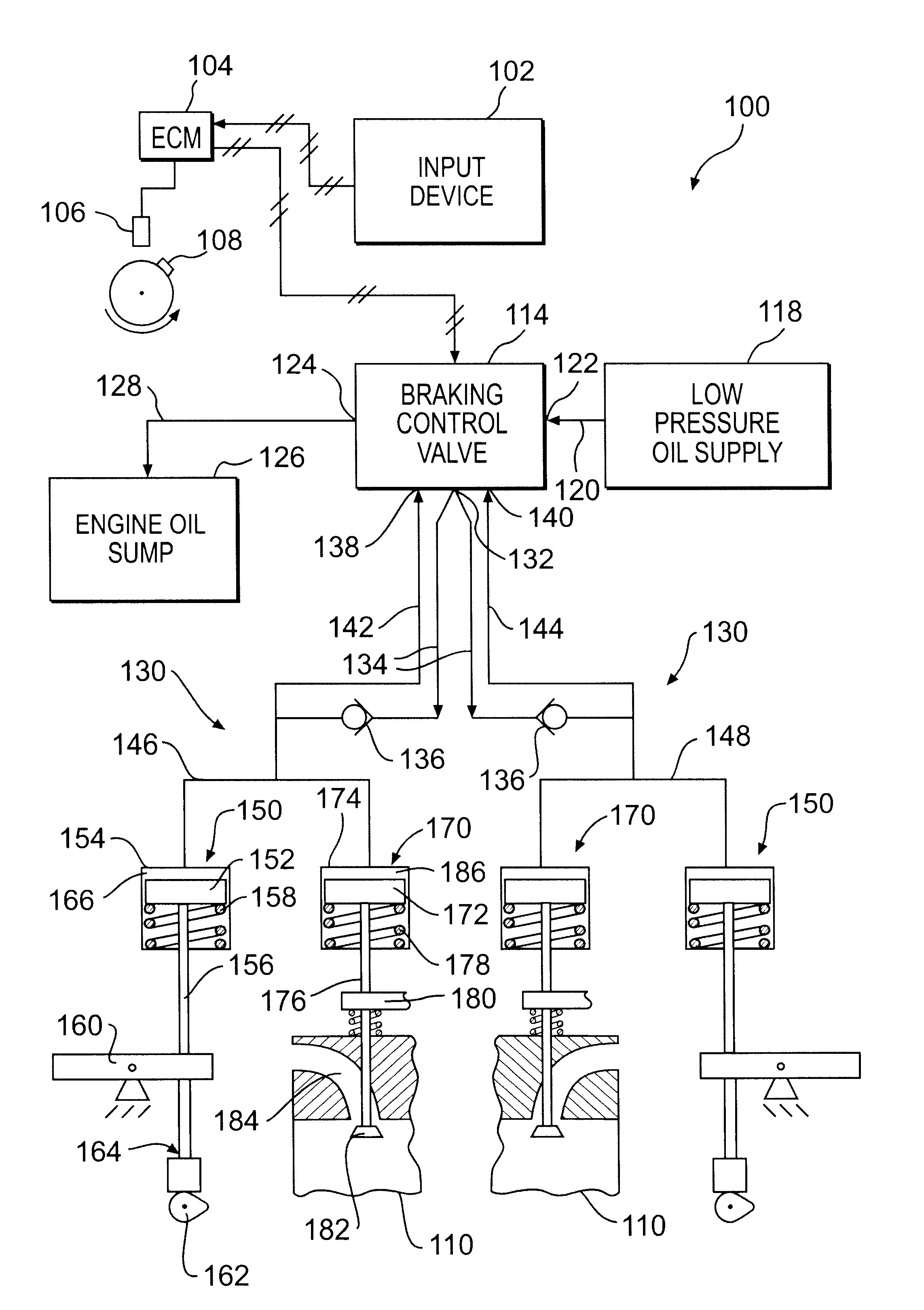
Referring now to FIG. 1, an engine braking system 100, for example, an engine compression braking system, for a multi-cylinder engine (not shown) is disclosed. The engine braking system 100 includes an input device 102 electrically coupled to an electronic control module (ECM) 104. The input device 102 may be, for example, a selectively switchable control available in an operator compartment of a vehicle, an automatic switch associated with a vehicle brake pedal, or any known method of providing an input signal. Optionally, the engine braking system 100 may include a sensor 106 configured to sense a crankshaft position indicator 108. The indicator 108 may be correlated to a top-dead-center position of each piston (not shown) in a cylinder 110 of the engine.

The ECM 104 is electrically coupled to one or more braking control valves 114. Although only one braking control valve 114 and two cylinders 110 are shown for simplicity, it should be understood that more than one braking control ...


PUM


Abstract

An engine braking system for a multi-cylinder engine includes a supply of low pressure fluid and an engine fluid sump. A plurality of valve actuators are each configured to be alternatively fluidly coupled to the supply of low pressure fluid and the engine fluid sump. Each valve actuator is operably coupled to at least one exhaust valve for a respective cylinder. The system also includes a braking control valve operably coupled to two of the valve actuators. The braking control valve is movable between a first position at which the two valve actuators are fluidly coupled to the engine fluid sump and blocked from the supply of low pressure fluid and a second position at which the two valve actuators are fluidly coupled to the supply of low pressure fluid and blocked from the engine fluid sump.

Description

TECHNICAL FIELDThis invention relates generally to engine braking systems and methods and, more particularly, to a control valve for engine braking systems and methods.BACKGROUNDEngine brakes, or engine retarders, are sometimes used to assist and supplement wheel brakes in slowing heavy vehicles, such as dump trucks, construction vehicles, tractor-trailers, and the like. Engine compression brakes convert an internal combustion engine from a power generating unit into a power consuming air compressor. Compressed air from the compression stroke of the engine is released through the cylinder exhaust valve when the piston in the cylinder nears the top-dead-center position. In conjunction with the increasingly widespread use of electronic controls in engine systems, engine braking systems have been developed which are electronically controlled by a central engine control unit.U.S. Pat. No. 3,220,392 issued to Cummins on Nov. 30, 1965, discloses an engine braking system in which an exhaus...

Claims


Application Information

Patent Timeline
IPC IPC(8): F01L9/00F01L9/02F01L13/06F01L9/10
CPCF01L9/02F01L13/065F01L2760/00F01L9/10
Inventor COTTON, III, CLIFFORD E.
Owner CATERPILLAR INC
Learn More