Bar code reader with an integrated scanning component module mountable on printed circuit board

a bar code reader and integrated scanning technology, applied in the field can solve the problems of increasing material and labor costs, increasing electrical power requirements, and insufficient useful life for some applications, and achieve the effect of enhancing the state-of-the-art of high-speed scanning arrangements

Inactive Publication Date: 2003-11-18
SYMBOL TECH LLC
View PDF7 Cites 23 Cited by
  • Summary
  • Abstract
  • Description
  • Claims
  • Application Information

AI Technical Summary

Benefits of technology

It is a general object of the present invention to enhance the state-of-the-art of high speed scanning arrangements, and particularly although not exclusively for such arrangements for use in optical scanners for reading indicia of differing light reflectivity, particularly laser scanners for reading bar code symbols.

Problems solved by technology

The use of two separate scanning motors and control means to produce the multi-axis and omni-directional scanning pattern increases material and labor costs as well as the amount of electrical power needed to operate the scanner.
In addition, the relatively complicated motor shaft and bearing arrangements of the scanning components may result in a useful life that is inadequate for some applications.

Method used


Image

  • Bar code reader with an integrated scanning component module mountable on printed circuit board
  • Bar code reader with an integrated scanning component module mountable on printed circuit board
  • Bar code reader with an integrated scanning component module mountable on printed circuit board

Examples


Embodiment Construction

:

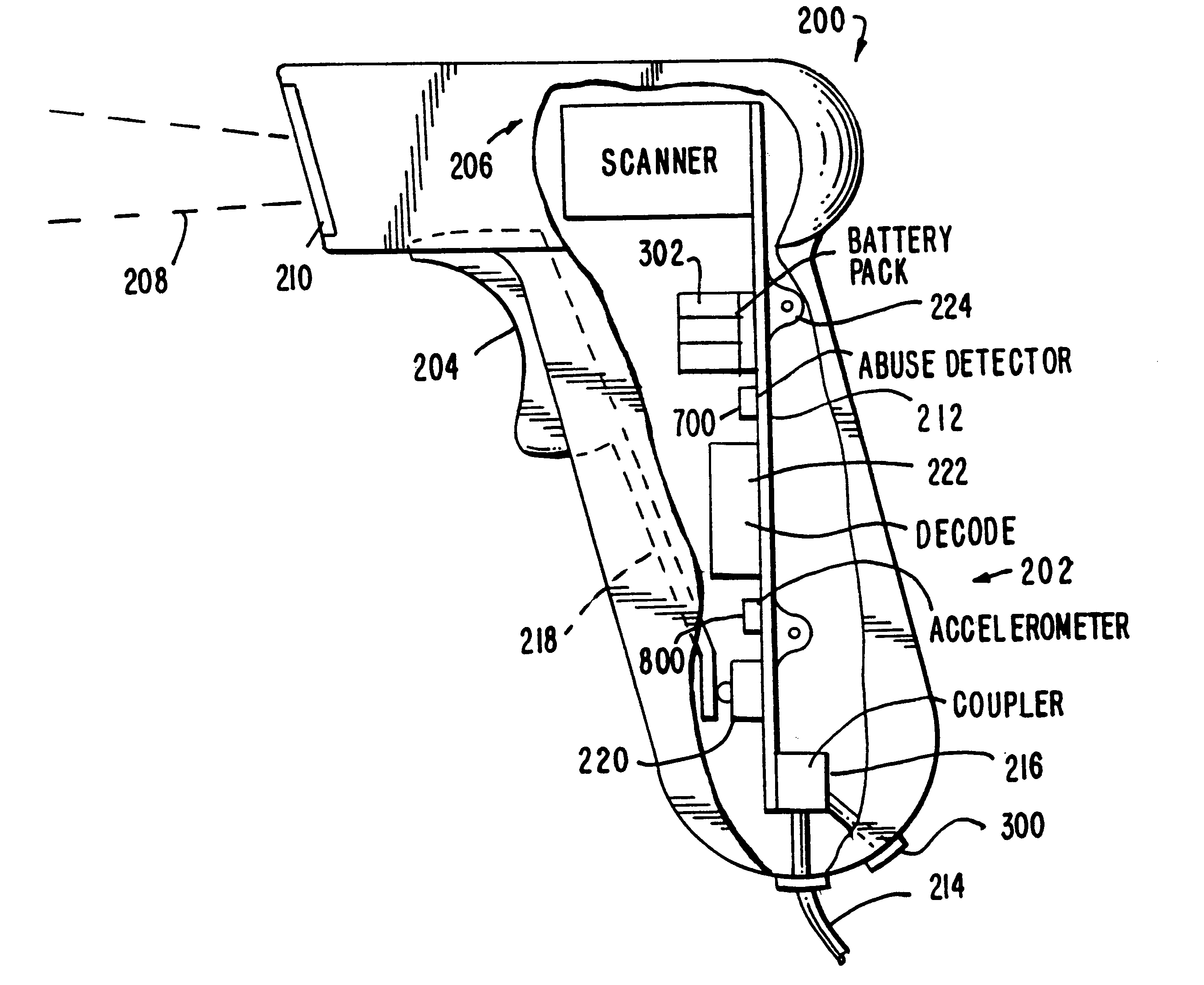
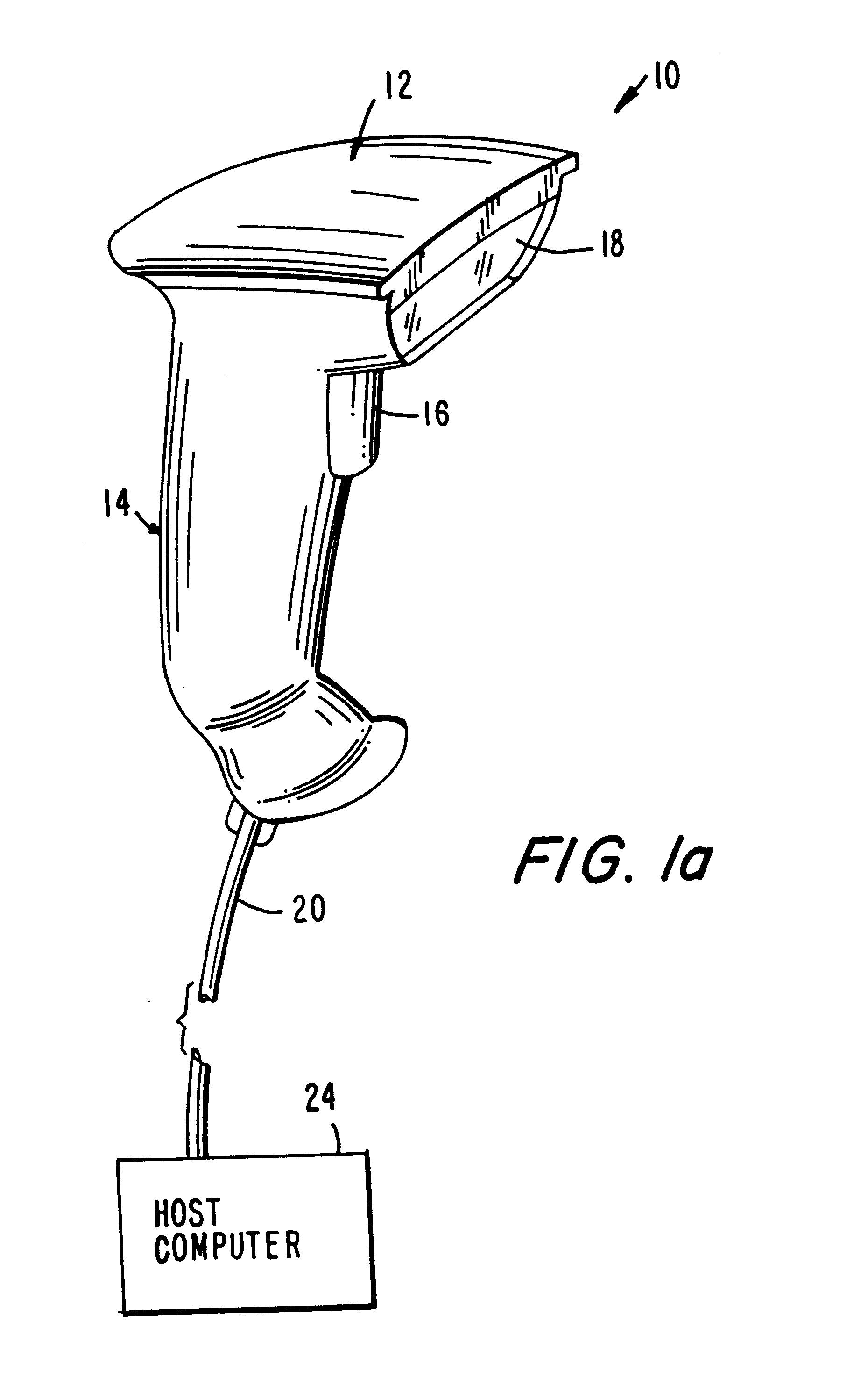
Referring now to the drawings, as shown in FIG. 1, reference numeral 10 generally identifies a hand-held scanner having a head 12 and an ergonomically-shaped handle 14. A manually-operable trigger 16 is situated below the head 12 on an upper, forwardly-facing part of the handle 14. As known from the above-identified patents incorporated by reference herein, a light source component, typically, but not necessarily, a laser, is mounted inside the head 12. The light source emits a light beam along a transmission path which extends outwardly through a window 18 that faces indicia, e.g. bar code symbols, to be read. Also mounted within the head is a photodetector component, e.g. a photodiode, having a field of view, and operative for collecting reflected light returning through the window 18 along a path from the symbol.

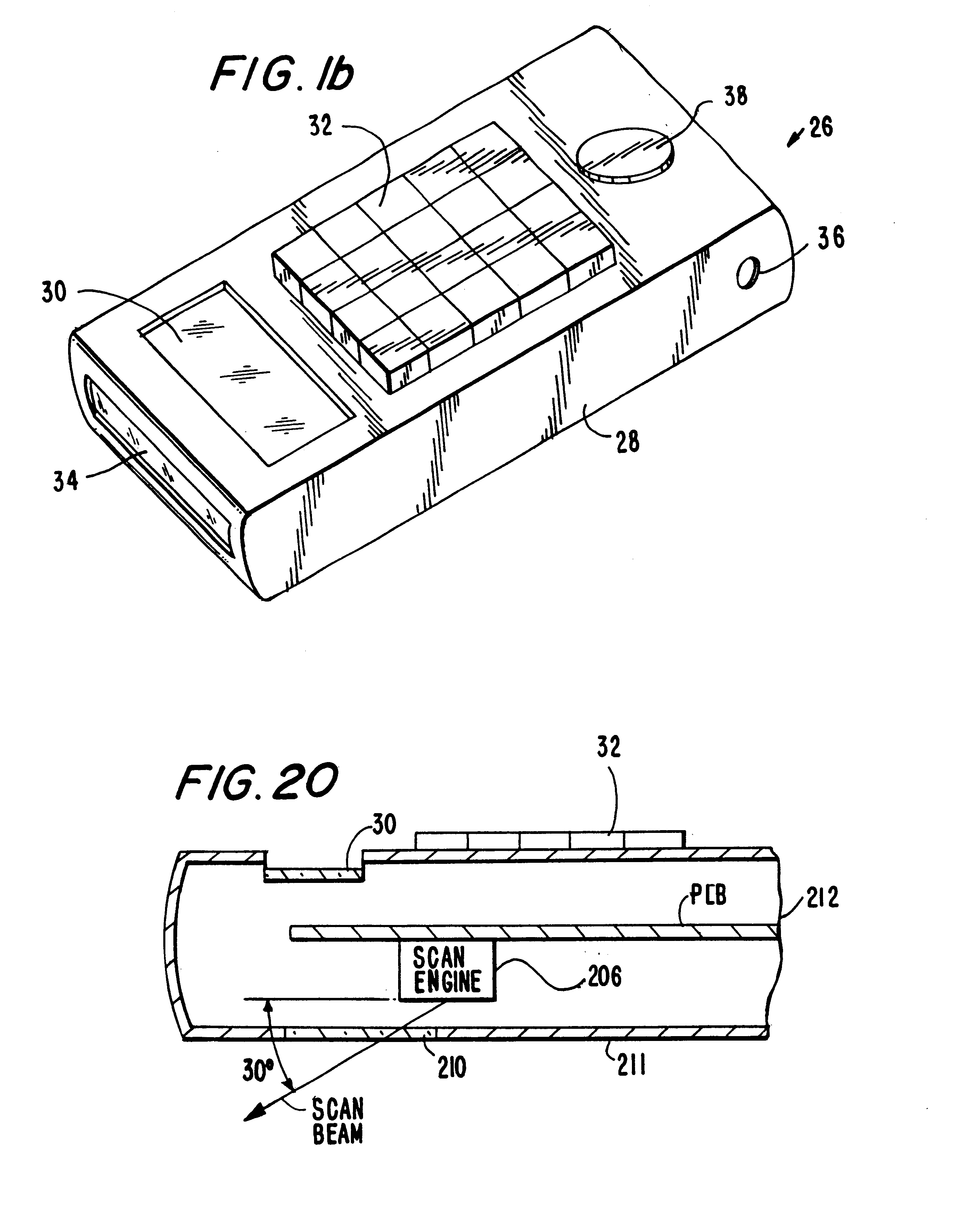
A scanner component (to be described in more detail with reference to FIG. 2) is mounted within the head 12, and is operative for scanning the symbol and / or the field of...


PUM


Abstract

A bar code reader has an integrated scanning component module which is mountable on a printed circuit board. In one embodiment, the module may include the digitizer/decoder electronics, enabling the module to be used with a generic PCB. In some embodiments, the module includes a high speed optical scanning arrangement having an optical element which extends longitudinally of a flexible member, secured at one end. In other embodiments, the invention extends to a hand-held optical scanner having a scanning assembly, detector and data transmission coupling all mounted to a common printed circuit board, preferably located within a manually-graspable handle. In yet a further embodiment, an abuse-detector or accelerometer is provided for determining when the device is exposed to deceleration above a predetermined limit, and optionally for automatically shutting down applications programs and for providing a black-box-record of a short time frame before the device was exposed to an unexpected shock. Preferably, the reader is shock protected by a thermo-plastic elastomer housing section. An outgoing light beam is directed at a non-orthogonal angle relative to the PCB.

Description

1. Field of the InventionThe present invention relates generally to a high-speed scanning arrangement, and particularly although not exclusively to such a scanning arrangement for use in hand-held or fixed optical scanners such as bar code scanners. In one embodiment the invention relates to a bar code reader with an integrated scanning component module mountable on a printed circuit board.2. Description of the Related ArtVarious optical readers and optical scanners have been developed heretofore to optically read bar code symbols applied to objects in order to identify the object by optically reading the symbol thereon. The bar code symbol itself is a coded pattern comprised of a series of bars of various widths and spaced apart from one another to bound spaces of various widths, the bars and spaces having different light reflecting properties. The readers and scanners electro-optically decoded the coded patterns to multiple digit representations descriptive of the objects. Scanner...

Claims


Application Information

Patent Timeline
Patent Type & Authority Patents(United States)
IPC IPC(8): G06K7/10G06V30/224
CPCG06K7/10633G06K7/10653G06K7/1098G06K7/10881G06K7/10851
Inventor DVORKIS, PAUL
Owner SYMBOL TECH LLC
Why Eureka
Try Eureka