Plain bearing

a bearing and plain technology, applied in the field of plain bearings, can solve the problems of increasing the true specific load of the bearing unfavorably, reducing the load capacity of the bearing to an unacceptable degree, and unable to avoid the occurrence of etc., to prevent premature wear and/or seizure, suppress the decrease in the load capacity, and reduce the area

Inactive Publication Date: 2003-11-18
DAIDO METAL CO LTD
View PDF12 Cites 17 Cited by
  • Summary
  • Abstract
  • Description
  • Claims
  • Application Information

AI Technical Summary

Benefits of technology

Another of them is a light weight design of the engine for recent vehicles. That is, due to the light weight design of the engine, the aluminum alloy is used in many members constituting the engine, or a bearing housing portion for securing the bearing is made to be thin in thickness. This light weight design is also applied to the connecting rod 1, so that a rigidity of the large end portion 2 tends to be reduced. Further, due to this reduction of the rigidity, the large end portion 2 finally receiving the load applied to the plain bearing 3 is elastically deformed, so that the whole of the plain bearing 3 is elastically deformed in the radial direction thereof to thereby have a convex shape such as that of a barrel. Thus, the bearing face itself is deformed to have an arcuate, concave shape in axial cross section.
The present invention is achieved by taking the matter explained above into consideration, and an object of the invention is to provide a plain bearing which can prevent a shaft from abutting against the end portions of the plain bearing due to the elastic deformation of the bearing alloy layer and / or of the bearing housing, while suppressing the decrease in the load-bearing capacity of the plain bearing.
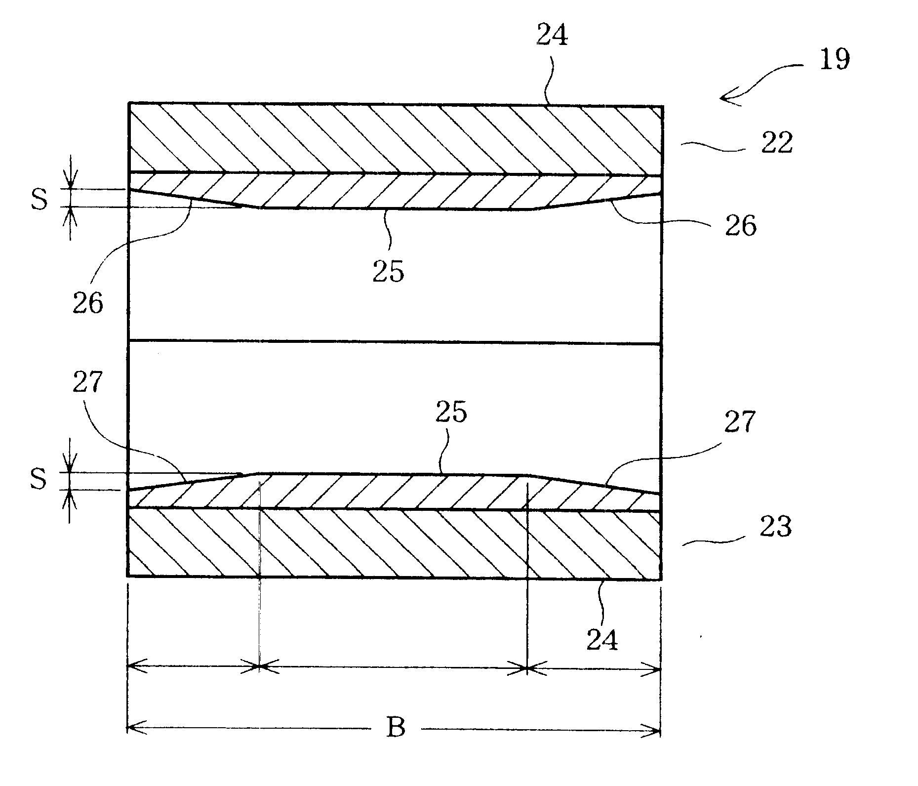
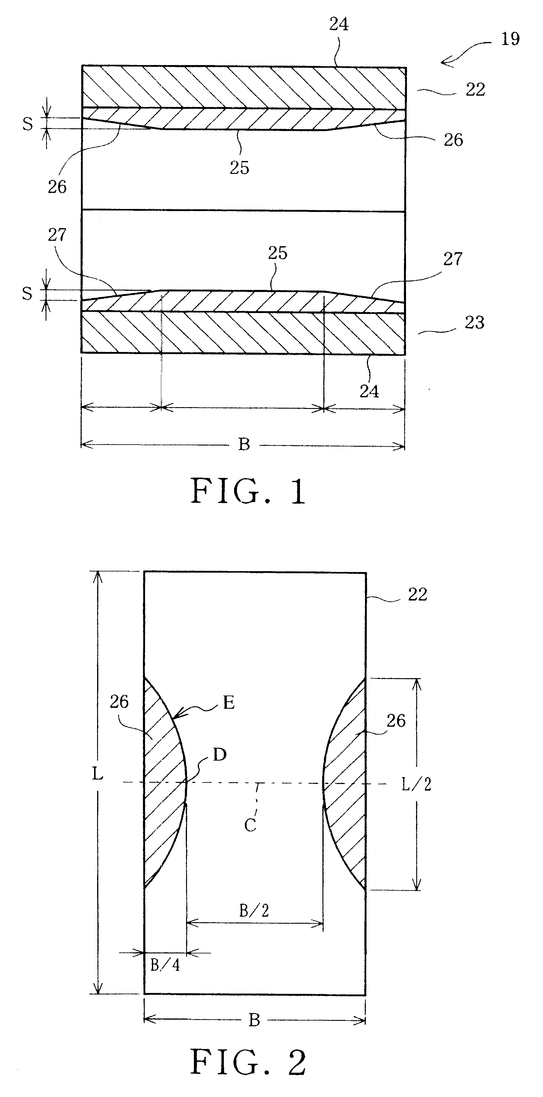
In the plain bearing according to the first aspect of the invention, since at least one inclination face inclined radially outwardly from the axially predetermined location defined between both ends of a bearing face toward the end of the bearing face is formed in each of the axially terminal sides of the bearing face in such a manner as to have different, axial lengths in respective portions defined along the circumference of the cylindrical bearing face, it is possible to compensate the elastic deformation of the bearing alloy layer and / or the bearing housing. That is, since the axial length of the inclination face along the circumference of the bearing face are selected to compensate the elastic deformation varying along the circumference of the bearing face, it is possible to minimize the area in which the inclination face is provided. Accordingly, it is possible to compensate the elastic deformation of the bearing alloy layer and / or the bearing housing while suppressing the decrease in the load capacity of the plain bearing, and it is possible to prevent the premature wear and the seizure.
According to the second aspect of the invention, there is provided a plain bearing set forth in the first aspect of the invention, in which the 
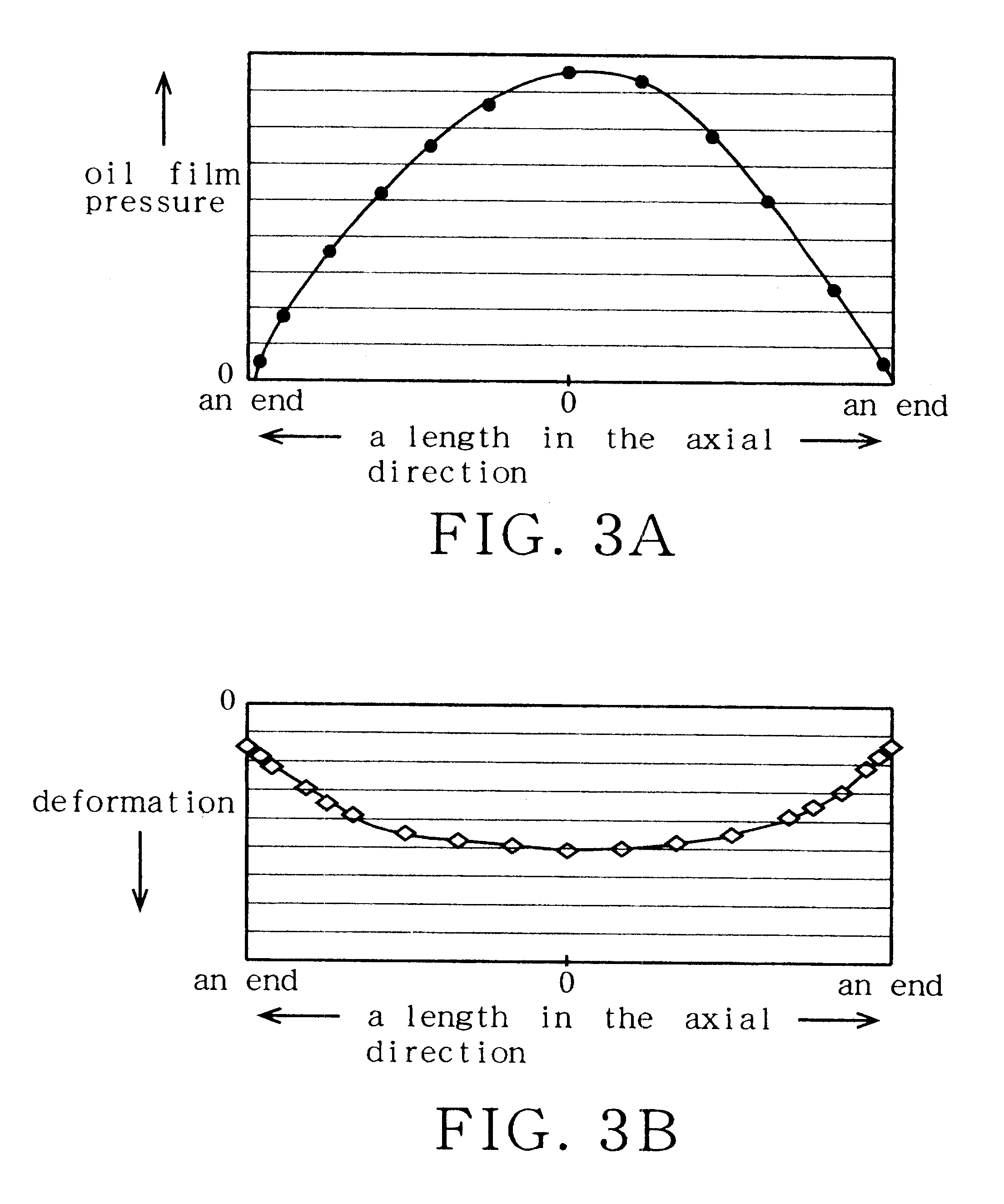
axial length of the inclination face is longest at an axially extended portion of the bearing face at which portion an oil film pressure becomes maximum, and in which plain bearing the axial length of the inclination face decreases as being spaced apart circumferentially from the location of the maximum oil film pressure. That is, in a case where the rigidity of the bearing housing is relatively low in the axial direction of the plain bearing, the axial length of the inclination face is selected so that the axial length thereof may become longest at the portion having a maximum oil film pressure in the bearing face and so that the axial length thereof may be decreased as being spaced apart therefrom in the circumferential direction. In the case of the plain bearing, the bearing face of the plain bearing is deformed in a arcuate concave shape in axial cross section with a deepest position being present at the maximum oil film pressure portion, however, according to the structure of the second aspect of the invention the axial length of the inclination face is made to be longest at the maximum oil pressure portion, so that it is possible to minimize the abutting of the shaft against both axial end portions of the bearing face.
According to the third aspect of the invention, there is provided a plain bearing set forth in the first aspect of the invention, in which the axial length of the inclination face is shortest at an axially extended portion of the bearing face at which portion an oil film pressure becomes maximum, and in which plain bearing the axial length of the inclination face increases as being spaced apart circumferentially from the location of the maximum oil film pressure. That is, in another case where the rigidity of the bearing housing is relatively high in the axial direction of the plain bearing (as shown in FIG. 6), the degree of the elastic deformation of the concave shape occurring at the maximum oil pressure portion of the bearing face is small, so that the axial length of the inclination face can be made to be short at the portion having a maximum oil film pressure in the bearing face. Thus, since the area of a bearing face portion adapted to bear the load of the shaft can be increased at the maximum oil film pressure portion, it is possible to make the axial length of an inclination face portion other than that of the maximum oil film portion long so that the bearing area of the bearing face may be reduced. Since, in the bearing face portions (other than the maximum oil pressure portion) in which the axial length of the inclination face is increased, it is possible to reduce the area of the bearing face adapted to receive a shearing resistance of the oil film without large decrease in the load-bearing capacity of the plain bearing, it is possible to reduce the friction loss of the plain bearing.

Problems solved by technology

However, since the conventional crowning C is provided for compensating the deflection of the crank pin 4, it is impossible to address the problem of the unfavorable abutment occurring due to the elastic deformation of the bearing alloy layer 5 and / or the elastic deformation of the large end portion 2 of the connecting rod 1, so that there occurs the problem that it is impossible to avoid the occurrence of the premature wear and / or the seizure.
As means for addressing the problem, it appear advisable to increase in the axial direction an area forming the crowning C. However, since the area in which the lubricating oil film is formed is reduced insofar as this means is concerned, a load-receiving area is reduced with the result the true specific load of the bearing is increased unfavorably, so that the load capacity of the bearing becomes reduced to an unacceptable degree.

Method used


Image

  • Plain bearing
  • Plain bearing
  • Plain bearing

Examples


first embodiment

a plain bearing embodying the invention for a crank pin mounted to a connecting rod of an engine for a vehicle is described below while referring to FIGS. 1 to 5.

FIG. 4 shows the whole of the connecting rod. In FIG. 4, a connecting rod 11 is constituted such that a cap 13 is fixed to one wide end portion of a rod main body 12 by bolts 14. In this connecting rod 11, a large end portion 15 constituted by one end portion of the rod main body 12 and the cap 13, and a small end portion 16 corresponding to another end portion of the rod main body 12 act as bearing housings, and plain bearings 19 and 20 are mounted within fitting holes 17 and 18 formed in the large end portion 15 and the small end portion 16, respectively.

In the plain bearings 19 and 20, the plain bearing 19 of the large end portion 15 acts to receive a crank pin (refer to FIG. 5) of a crank shaft, and the plain bearing 20 of the small end portion 16 acts to receive a piston pin (not shown) assembled in the piston. The pla...


PUM


Abstract

There is disclosed a plain bearing comprising: a back metal; and a bearing alloy layer bonded onto the back metal which bearing alloy layer is provided at a surface side thereof with a cylindrical bearing face extended in the direction of the axis of the plain bearing, the bearing alloy face being provided at each of axial terminal portions thereof with an inclination face inclined radially outwardly from a location defined between both of axially terminal ends of said bearing face toward said axially terminal ends thereof, the inclination face having an axial length varying along the circumference of the inclination face.

Description

BACKGROUND OF THE INVENTIONThe present invention relates to a journal plain bearing in which a bearing alloy layer is provided on a back metal, and more particularly to a plain bearing in which the wear resistance and anti-seizure property are improved.For example, in a plain bearing used in an engine for a vehicle, a taper-shaped crowning shown by reference symbol "C" in FIG. 10 is provided in both of the axially end portions of a bearing face. The reason why the crowning C is provided is explained below.FIG. 11, for example, shows a bearing structure in the side of the large end portion of a connecting rod. The connecting rod 1 acts to receive the combustion pressure of a fuel from a piston and to transmit the combustion pressure to a crank side. In the connecting rod 1, a plain bearing 3 is provided in the large end portion 2, and a crank pin 4 is supported by the plain bearing 3. The crank pin 4 is bent to have a circular arc shape due to the combustion pressure applied thereto ...

Claims


Application Information

Patent Timeline
Patent Type & Authority Patents(United States)
IPC IPC(8): F16C9/00F16C9/04F16C33/04F16C33/12F16C17/02F16C23/04F16C33/06F16C33/10
CPCF16C9/04F16C33/122F16C17/022F16C23/041F16C2240/50F16C9/00
Inventor OKAMOTO, YUTAKAIMAI, SATOSHIHIRAMATSU, NOBUTAKAISHIKAWA, HIDEOSHIBAYAMA, TAKAYUKIKITAHARA, KEN
Owner DAIDO METAL CO LTD
Why Eureka
Try Eureka