Measurement system and method

a measurement system and flue technology, applied in the field of flue measurement, can solve the problems of increasing the potential for a blowout, reducing the hydrostatic pressure, and affecting the flow rate of fluids,

a measurement system and flue technology, applied in the field of flue measurement, can solve the problems of increasing the potential for a blowout, reducing the hydrostatic pressure, and affecting the flow rate of fluids,

US6650280B2Inactive Publication Date: 2003-11-18NASA

Image

  • Measurement system and method
  • Measurement system and method
  • Measurement system and method

Examples


Embodiment Construction

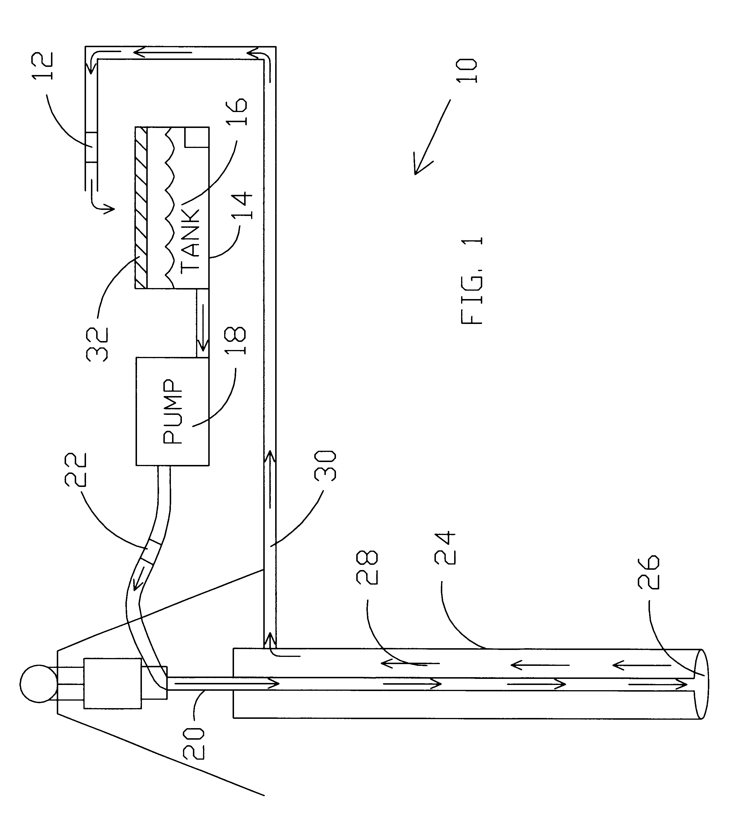
In one presently preferred embodiment of the invention, a primary object of a mass measuring system is to measure the entrance and the exit masses of drilling fluid while drilling a well hole. After the input mass of the fluid is determined, the added or lost mass at the exit reveals the mass being generated or lost during drilling. This should provide early warning of trouble during the drilling process and possibly avoid the loss of a hole.

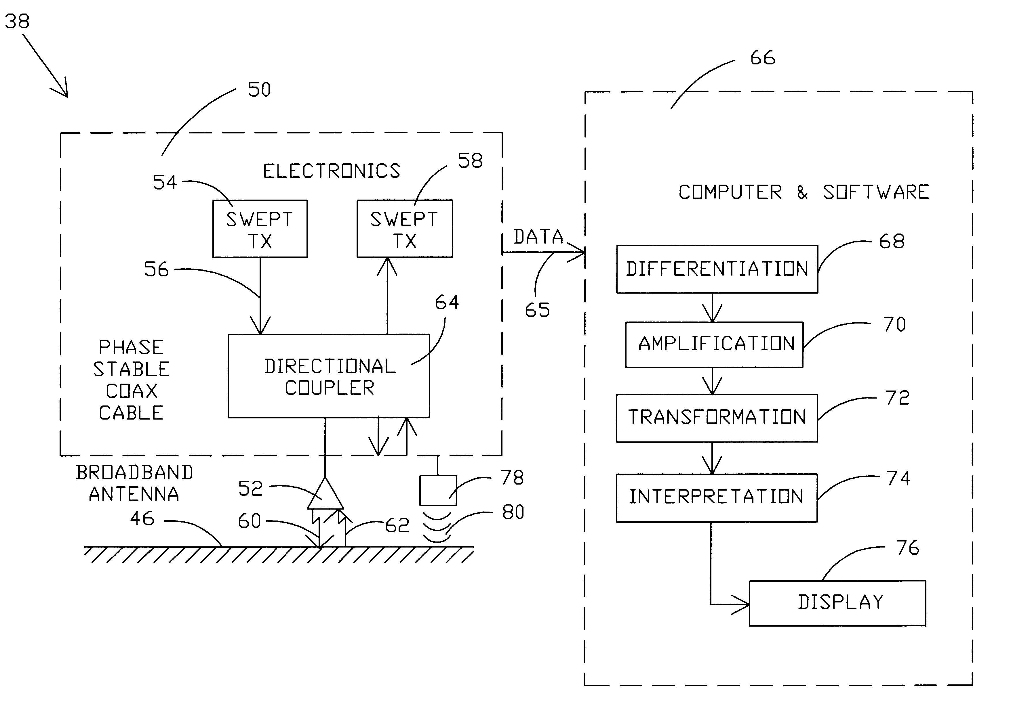
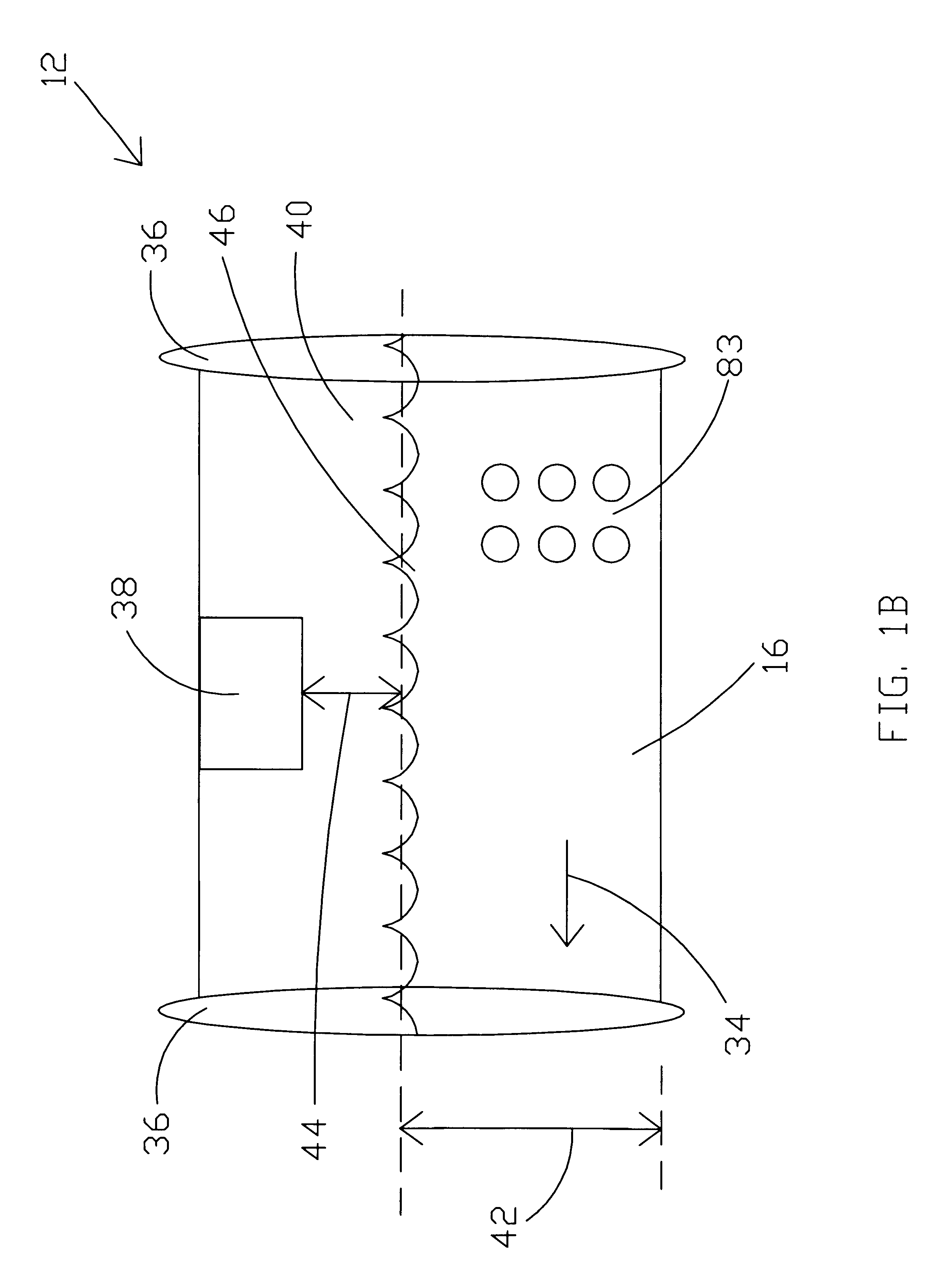
The present invention provides a sensing system that can provide accurate volume and density measurements of drilling fluid in one or more locations of the drilling fluid circulation stream as the drilling fluid is circulated into and out of the wellbore during drilling operations. To determine mass flow, the present invention preferably determines fluid velocity and density and then calculates instantaneous mass flow and / or mass flow over a selected time period. In one preferred embodiment of the invention, the entire fluid flow is measured. Al...


PUM


Abstract

System and methods are disclosed for fluid measurements which may be utilized to determine mass flow rates such as instantaneous mass flow of a fluid stream. In a preferred embodiment, the present invention may be utilized to compare an input mass flow to an output mass flow of a drilling fluid circulation stream. In one embodiment, a fluid flow rate is determined by utilizing a microwave detector in combination with an acoustic sensor. The acoustic signal is utilized to eliminate 2pi phase ambiguities in a reflected microwave signal. In another embodiment, a fluid flow rate may be determined by detecting a phase shift of an acoustic signal across two different predetermined transmission paths. A fluid density may be determined by detecting a calibrated phase shift of an acoustic signal through the fluid. In another embodiment, a second acoustic signal may be transmitted through the fluid to define a particular 2pi phase range which defines the phase shift. The present invention may comprise multiple transmitters / receivers operating at different frequencies to measure instantaneous fuel levels of cryogenic fuels within containers positioned in zero or near zero gravity environments. In one embodiment, a moveable flexible collar of transmitter / receivers may be utilized to determine inhomogenuities within solid rocket fuel tubes.

Description

1. Field of the InventionThe present invention relates generally to fluid measurements and, more specifically, to a fluid measurement system that may be utilized for making mass measurements during fluid flow. The present invention also has application in reduced and zero gravity environments and for finding discontinuities in an otherwise homogeneous material.2. Background of the InventionIt is well known that when drilling wells for hydrocarbons, a standard drilling practice involves circulating drilling fluid from the surface downwardly through the drilling string. The drilling fluid emerges at the drill bit and returns to the surface through the annulus in the wellbore on the outside of the drilling string. The drilling fluid performs many functions, some of which are discussed herein. The drilling fluid cools and reduces friction of rotating the drilling string. The drilling fluid removes excavated material from the wellbore in the circulation stream flowing to the surface. The...

Claims


Application Information

Patent Timeline
18 Nov 2003
Publication
US6650280B2
IPC
G01F23/296; G01F25/00; G01F23/284; G01S15/58; G01S15/00; G01S13/00; G01S15/10; G01S13/10; G01S13/86
CPC
G01F23/284; G01F23/2962; G01F25/0061; G01S13/862; G01S15/101; G01S15/584; G01S13/10; G01F25/20
Inventors
ARNDT, G. DICKEY; NGO, PHONG H.