Alignment clamp

a technology of aligning clamps and clamping rods, applied in the direction of soldering apparatus, manufacturing tools, auxillary welding devices, etc., can solve the problems of preventing damage to the connecting workpiece, unable to meet the needs of use, so as to facilitate tightening and loosening, efficient alignment and joining

Inactive Publication Date: 2003-11-25
BARBER FRLIN R
View PDF59 Cites 39 Cited by
  • Summary
  • Abstract
  • Description
  • Claims
  • Application Information

AI Technical Summary

Benefits of technology

A primary object of the present invention is to simply and efficiently align and join a variety of pipe, tube, bar, fittings, and other workpieces, in a variety of sizes and cross-sections, utilizing a minimum of moving parts, a minimum of tightening tools, and a minimum of adjustments.
A related object of the invention is the alignment of workpieces in congested spaces and awkward positions, including spaces and positions where prior art devices have historically not worked well.
A third object of the invention is simplicity and economy of manufacture, using combinations of parts capable of withstanding neglect and abuse, by tradespersons and others.
A fourth object of the invention is ease of use, by operators having a wide variety of aptitude and skill, or, in some cases, having no skill at all.
Optionally, to prevent damage to the connecting work piece, each adjustable fastener can have a depression, in the area where the adjustable fastener contacts the connecting workpiece, also known as the fastener contact area. Further variations with this feature are possible. The adjustable fastener can have an indentation in its head, to facilitate its tightening and loosening, by a tool or other fitting. The detent assembly, optionally, can have a detent cap. The detent cap, in turn, can have an indentation at its center, to facilitate its tightening and loosening, by a tool or other fitting. The detent cap can also have a hole, to permit lubrication of the detent assembly, while excluding debris. Optionally, for ease of use, the flexible member can have a cruciform cross-section, or be colored according to a range of actual or expected first workpiece cross-sectional perimeters. Also, the plunger assembly can be hardened.
In another form of the invention, a clamp assembly includes the combination of a to flexible member, a lockable tool, and an alignment apparatus. Again, the alignment apparatus is made up of an alignment bar assembly, a detent assembly, and at least one adjustable fastener. The flexible member, in this form, is cruciform in cross-section, with a corresponding cruciform-shaped slot in the alignment bar assembly, to facilitate the sliding of the alignment apparatus on, off, or along the flexible member. A lockable tool is used here to grip and clamp, or grippingly clamp, the flexible member about the first workpiece, and secure it about the first workpiece. The alignment bar assembly contacts the first workpiece, and overlies the connecting workpiece. In this form of the invention, a detent assembly utilizes a spring, to bias a plunger assembly along a detent casing, and through an upper hole in the alignment bar assembly, causing the plunger assembly to engage the flexible member, and restraining the movement of the alignment apparatus along the flexible member. The spring biasing force can be varied, by adjusting the detent cap that restrains the spring. Each connecting workpiece is aligned with the first workpiece, using an adjustable fastener mounted on each alignment bar assembly. Once aligned, the first workpiece can be joined to each successive connecting workpiece, by welding or other means.

Problems solved by technology

In the fabrication, construction and repair trades, there has persisted a very real problem of pre-positioning and holding a pair of pipe sections together, prior to their joining by welding or other permanent attachment.
The problem has been compounded for pipes, fittings, and other workpieces of non-circular cross-section, since the prior art has tended to focus on circular pipe.
Pipe sections, tube sections, solid sections, and workpieces of other cross-sections can be quite heavy, and it can be difficult, under the best of circumstances, to align successive sections, to hold a connecting section in exact alignment with, and, in appropriate space relationship with, its prior section.
This problem is exacerbated in tight work areas, such as buildings, and with vertical or near-vertical workpieces, such as stack pipes or poles.
Small workpieces, at the other end of the spectrum, may be lighter to hold, but harder to handle, due to placement in confined areas, or areas partially or mostly inaccessible to the tradesperson.
This situation is complicated when the tradesperson must align and / or attach pipe of varying outer diameters, having the same inner diameter.
The situation is also complicated when the tradesperson must align and / or attach various forms of fittings, including, but not limited to, elbows, reducers, tees, crosses, caps, stubs, rings, flanges, and weldments.
However, the heavy, rigid frame and rotatable handle of the Hickey clamps require substantial working room and storage room.
The use of rigid clamps, however, is limited to a single size of circular pipe.
Furthermore, such clamps have a tendency to be bulky and heavy, especially for larger pipe diameters.
Unaddressed problems have persisted with the chain approach, nevertheless.
Slender, threaded shafts, and intermeshing gear means have been attempted, as disclosed by Mori, but slender shafts have a tendency to break under heavy use, and intermeshing gear means can be difficult to adjust, especially when placed close to the workpiece.
Attempts have been made to utilize alignment plates permanently joined to the chain, as disclosed in the Olson and Haywood patents, but permanently-joined plates are not adjustable along the chain, for different sizes of pipe.
Other attempts have been made to mount alignment devices on the chain using wires, as shown in the Watson '159 patent, but complications arise from the fragility of the mounting wire, and the lack of bearing area between the chain and the alignment device.
The lack of bearing area can lead to rotation and wobble of the alignment device as the chain is tightened.
Handcranks, however, cannot be fitted in small, congested, or difficult-to-reach workspaces.
The jack bars disclosed to date can be complex to make, and easy to abuse and break, due to the number and complexity of their components.
The size, weight, and complexity of the various prior-art combinations are ill-adapted for use on non-horizontal workpieces (such as vertical pipe, vertical shafts, or flagpoles), or small size workpieces.
A large clamp, and its component crank, can dwarf, or even damage a small workpiece.
Excessive lengths of chain can interfere with the operator, particularly in tight spaces.
Rotation and wobble of the jackbar can occur during tightening of the chain, due to the gap between the chain and the jackbar, required for movement of the jackbar along the chain.
Overall, the prior art has taught towards greater complexity, and has not addressed the possibility of a slidable alignment of jack bar and chain without nuts, screws, or hand tools to adjust.
The prior art has also focused on pipe, to the exclusion of shapes other than circular pipe cross-sections, and has tended to use chain of rectangular cross section, compromising the stability of the alignment apparatus attached to it.
In addition, none of the above prior art has addressed the possibility of aligning more than two workpieces at a time.
This can create problems for pipe, fittings, and other workpieces made of titanium or other specialty metals, especially where installed in clean environments, such as food processing facilities, semiconductor assembly buildings, or pharmaceutical plants.
Sharp-pointed screws, as used in most of the prior art, can create scratches in the stock or pipe, either causing corrosion in the scratch, or allowing impurities to accumulate in the scratch.
Swivel feet could be mounted on the screws or nuts, as disclosed in the later Dearman patents, but would add to the cost and complexity of fabrication.

Method used


Image

  • Alignment clamp
  • Alignment clamp
  • Alignment clamp

Examples


Embodiment Construction

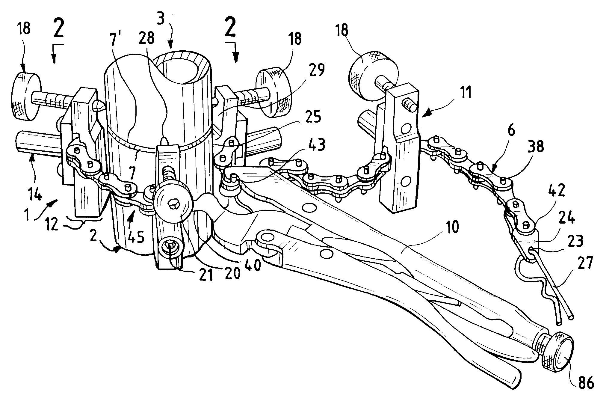
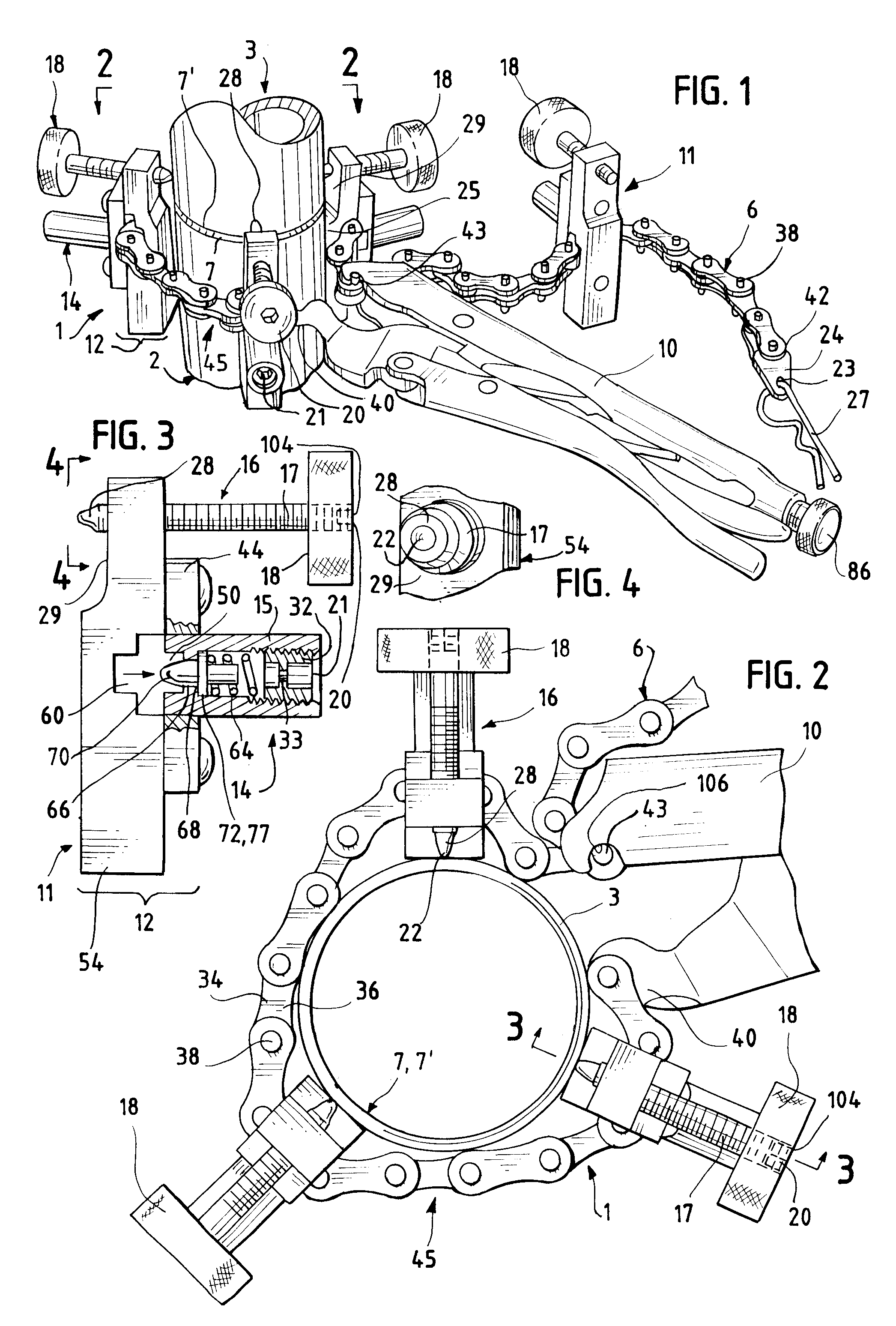
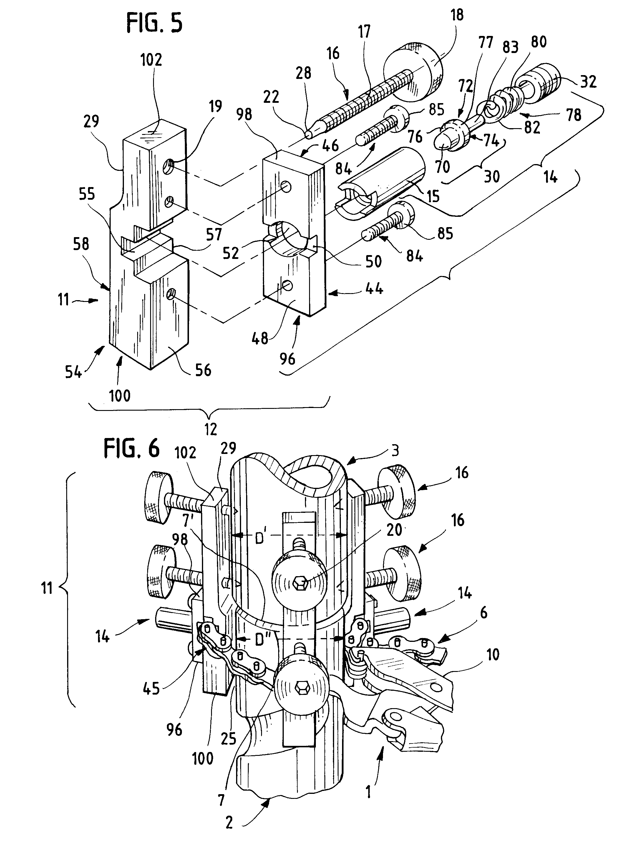
FIGS. 1 AND 2 depict a preferred embodiment of an alignment clamp assembly 1 in use, aligning a first confronting terminus 7 of a first workpiece 2, with a second confronting terminus 7' of a connecting workpiece 3. In FIG. 2, the first workpiece 2 is hidden behind the connecting workpiece 3.

In FIGS. 1 AND 2, the first workpiece 2, and the connecting workpiece 3, are vertical circular pipe sections. The workpieces 2, 3, 3' need not be horizontal or vertical, but may be in any position. FIG. 8 depicts the alignment clamp assembly of FIG. 1, in use on a pair of square bar workpieces 2, 3. Prior art has not shown an alignment clamp used on non-circular workpieces.

As shown in an equivalent embodiment depicted in FIG. 7, it is possible to use other, equivalent embodiments of the invention, to align more than two workpieces. Therefore, the term "connecting workpiece" should be defined to include the workpiece 3, or workpieces 3, 3', that will be aligned with the first workpiece 2, by a pa...


PUM

PropertyMeasurementUnit
diameteraaaaaaaaaa
outer diameteraaaaaaaaaa
flexibleaaaaaaaaaa

Abstract

A clamp for aligning the confronting ends of two or more workpieces, preparatory to their permanent joining. This clamp utilizes a chain of cruciform cross-section, and one or more alignment apparatuses, to encompass and secure the first workpiece, and align the remaining connecting workpiece(s). The chain may be fitted to the first workpiece, using color coding to select added chain-link sections for larger workpieces. Each alignment apparatus is slid on the chain, and secured by a spring-biased detent. The chain is then secured about the first workpiece. The alignment apparatus overlies the connecting workpieces, which are then aligned for joining, using one or more adjustable fasteners mounted on the alignment apparatus.

Description

Not applicable.STATEMENT REGARDING FEDERALLY-SPONSORED RESEARCH OR DEVELOPMENTNot applicable.REFERENCE TO A MICROFICHE APPENDIXNot applicable.BACKGROUND OF THE INVENTION-FIELD OF THE INVENTIONThis invention is directed to the temporary end-to-end alignment of two or more workpieces, such as tubing, pipe, handrail, fittings, shafts, or solid bar, to facilitate their permanent joining, by welding, brazing, soldering, adhesive application, or other physical or chemical means. This invention is intended to fulfill a long-felt need for an alignment device that is light, small, portable, interchangeable, easily maneuverable in confined spaces, and readily usable by pipefitters, millwrights, welders, plumbers, ironworkers, and other practitioners in the fabrication, construction, and repair trades, having a variety of skills and aptitudes.BACKGROUND OF THE INVENTION-DESCRIPTION OF PRIOR ARTIn the fabrication, construction and repair trades, there has persisted a very real problem of pre-po...

Claims


Application Information

Patent Timeline
Patent Type & Authority Patents(United States)
IPC IPC(8): B25B1/00B25B1/20B23K37/053B25B5/14B25B5/00
CPCB23K37/0533B25B27/16B25B5/147B25B1/205B23K2201/06B23K2101/06
Inventor BARBER, FRANKLIN R.
Owner BARBER FRLIN R
Why Eureka
Try Eureka